Continue to Site

Eng-Tips is the largest engineering community on the Internet

Intelligent Work Forums for Engineering Professionals

  • Congratulations KootK on being selected by the Eng-Tips community for having the most helpful posts in the forums last week. Way to Go!

Wood Columns...Possible or Bad Idea

Status
Not open for further replies.

Sokka10

Structural
May 31, 2021
28
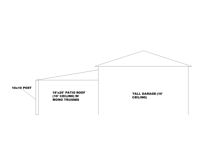
I already did the engineering for this residence a few months ago. The contractor has come back complaining about my design as it's not what he's used to seeing in this area. In his defense, he is correct about what I spec'd out not being the norm. What I did was engineer these three columns at this covered porch as cantilever steel columns. What he wants to do is have them be 10x10 wood columns.

We are in SDC D. In my mind I can't imagine how the lateral forces for this covered roof can be taken care of using wood columns, but I have a feeling that I am going to get bullied into changing them. Do you all have any ideas for how a wood column design could work? Options I can think of...

- Embedded posts: I don't like this idea (water issues). Also, I don't know how to analyze an embedded post system. Any references for how to do this?
- Knee braces at the columns: Owners don't want knee braces. Also, as others have pointed out in other threads, knee brace calcs don't ever work out.
- Knife Plate Connection at the bottom: Haven't done this before. No idea if this provides the needed fixity, and not sure how to analyze this either.

Most other engineers in my area would call these posts out as 6x6 columns without knee braces, and with standard post bases at the bottom. Are they crazy? Am I crazy?
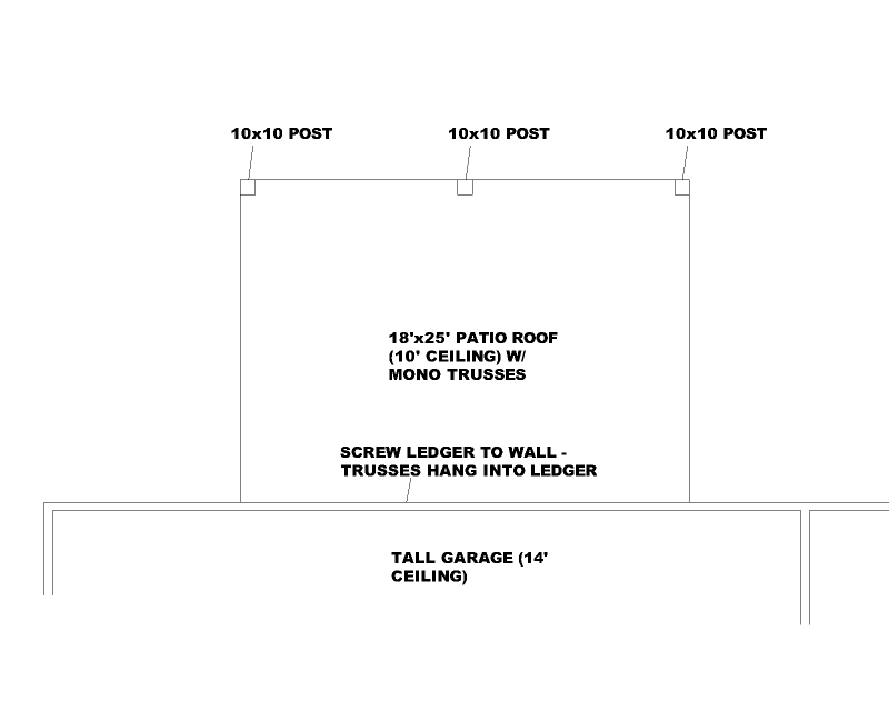
1_gwyiju.png
2_jsato3.png
 
Replies continue below

Recommended for you

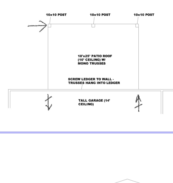
I don’t know the exact details but i guess it normally works like this (assuming diaphragm action from canopy roof). You would need to make sure you can follow the load path right through however.

8D9D29DA-3BA9-4DCE-9437-F479E88C86D1_keu3c8.jpg
 
I agree with MIStructE_IRE. I would be trying the diaphragm route first.
I run into this all the time with screened porches. Most engineers around my neck of the woods don't give it a second thought. We have shown moment frames on many occasions due to really bad aspect ratios or sketchy attachment conditions at the house.
 
MIStructE, do those crossed arrows denote reactions?

Sokka10, there are many methods for embedded post calculations. I'm pretty sure the IBC has one which may be the best for you to hang your hat on in the US but I'd need someone else to provide an exact reference. I've only read about it in this forum.

There are also a few recipes for avoiding deterioration too quickly. Here's one in Data Sheet 9, but check whether your climate is similar:

The knife plate could work if you only need moment connection in one direction. I've seen cruciform inserts but not a fan - seems too easy to get splitting. An alternative is a circular section up the middle if hidden connection is needed. Or a couple of big angles wrapped around opposite corners and bolted through the posts if visible connections are ok. For calculations, you treat as free body with some assumed distributed reaction such as linear with maximum equal to timber bearing strength.

This all assumes that MIStructE's solution to brace the posts doesn't pan out for some reason.
 
Sokka - for embedded posts, look at IBC chapter 18. I'm not sure what restrictions there are for seismic, though, so look into that.

Given the misalignment of the patio roof and the garage roof, you may have some issues with your lad path. You'd need some sizeable columns in the garage wall to take the reactions from the lower diaphragm since it can't be transferred directly into the upper one. The load path is critical there and, if the garage is already built, that may not be a viable option.

If the contractor didn't want to built a porch with steel columns, he shouldn't have bid the job. Don't let him bully you. If you can make it work in a more cost effective way, great, but if you can't then don't just give in. Make sure you can explain to the owner why, of course, because you can bet the contractor will be telling them how incompetent you are.

If you want to try wood, search on here for cantilevered wood column. There are a lot of threads that have discussed the topic, including merits of knife plate vs. cruciform, angles, Simpson Moment Bases, etc.
 
Yea, talk to the owner about how the contractor bid the design, and they should build it as such.
 
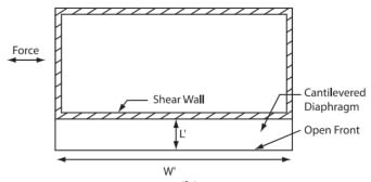
I had an epic battle with a plan reviewer in the SF bay area about analyzing a 12'x12' porch as a cantilevered diaphragm like MIStructE_IRE is showing. He absolutely insisted that it was not possible for a flexible diaphragm to transmit torsional moment to be resolved into a T/C couple at the walls. So I told him it was a rigid diaphragm, and not to forget that it's a porch. Phone call #3...He insisted that I prove that it can be classified as rigid, with the whole average diaph deflection/average story drift >= 2 (i think that's it?). I said "well, it's a 12'x12' square of 3/4" plywood - sounds pretty rigid to me." He didn't like that. I threw my hands up and put in Strongwalls. What a ridiculous porch....smh.

So...OP, if this porch is in Livermore, CA, be warned.
 
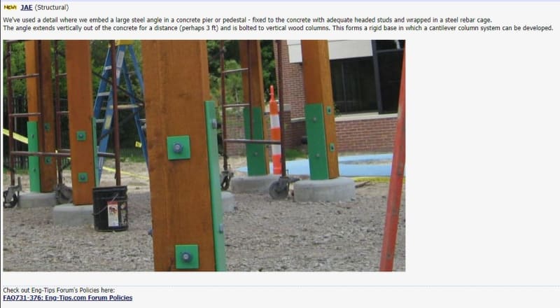
Here is one that "JAE" did several years ago. I copied the image because I thought it might come in handy one day.

He embedded steel angles in a footing or drilled shaft. Then, he through bolted the columns to the angles.

It looks like he alternated the orientation of the angles on different columns so that he could develop a moment capacity in both the X & Y directions.

Moment_Connection_Post_vmd6n0.jpg
 
So many questions...

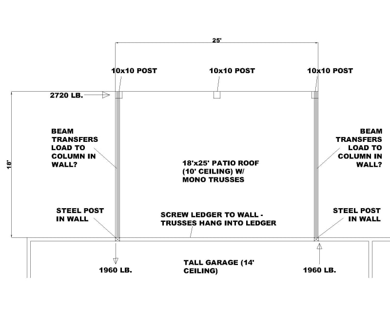
If I try the diaphragm route suggested by MIStructE_IRE then I guess my R value is 2.5 since I'd be tying it back into cantilever steel columns in the garage wall? I calculate the dead weight of this roof to be 6750 lb. (18' x 25' x 15 psf = 6750 lb.). With R=2.5 my seismic force is 2720 lb. which makes the reaction at each post in the garage wall = 1960 lb. as a force couple. Is this load transferred into the columns via beams as shown below? I don't think it will be possible to get a steel column in that wall capable of resisting that 1960 lb. and resulting moment at the base, which I think phamENG was alluding to.

I've looked at those Simpson moment bases before, the resistance they provide never comes even close to what I'd need for roofs like this. If I try the embedded post formulas from IBC Chapter 18 I'm getting some ridiculous embedment depths (~ 7-10 feet). I'm getting kind of pissed because as I said, most engineers in my area wouldn't design any lateral system for this roof, while I'm over here either making them do steel columns, or trying to convince myself that some half-assed, janky solution with wood columns will work. I haven't looked heavily into knife plates or something like that picture from JAE posted by JoelTXCive, but since I'm not very smart I don't know how I'd begin to calculate the moment capacity of a knife plate to wood post connection. I found these interesting cruciform post bases (Rothoblaas X10) but the moment capacities they give are pretty weak, just like the Simpson ones.

Porch_hphz4m.jpg
 
Could the posts in the garage wall be full height instead of cantilevered? Then the lateral load is delivered to the garage roof and the floor equally (ish). I don't know if that would change your R number as I don't deal in seismic, but it might make the detailing and sizing of the columns a bit more manageable.
 
dold said:
I had an epic battle with a plan reviewer in the SF bay area about analyzing a 12'x12' porch as a cantilevered diaphragm

You should have cited AWC SDPWS 4.2.5.1:

Screenshot_2_tfnatp.jpg

Screenshot_3_uvqnyp.jpg
 
@Sokka10 - double check where your seismic force is applied, half would be at the front columns and the other half at the building - correct? This may reduce your forces into the column at the building. For the building column, I would recommend a pin-pin scenario with a point load from the lateral where the low canopy roof connects to the column. Then the column needs a tie or some sort connecting it to the roof diaphragm, thereby dragging the load into the building roof diaphragm as two point loads. This way you are avoiding a moment connection all together.
 
Aesur said:
double check where your seismic force is applied, half would be at the front columns and the other half at the building
Yes, you are right and that would decrease the forces in the left-to-right direction. However, when the seismic load is applied perpendicular to where I currently show it, the forces into each wall column will be the same as I am showing them currently. A big consideration here is the R value though. If I say that I'm transferring the load into the roof diaphragm and then back into wood sheathed walls then I could use an R value of 6.5?

jayrod12 said:
Could the posts in the garage wall be full height instead of cantilevered?
Good idea. But let's say I try a 6x6 post in the wall. The post would effectively be a 14' long beam with a point load closeish to the midspan, right? Again, the R-value here will be a major factor as that point load could be anywhere from 700 lb. to 3000 lb. depending on the Seismic Force-Resisting System used per ASCE Table 12.2-1. But even if it's only 700 lb a 6" deep beam wouldn't be adequate for such a point load. Or duh, I guess I could do steel columns in the wall, and then have to figure out a way to attach the column to the wall to plates.
 
YEah I think you can get full height steel columns to work for that load. I would say likely quite easily. That load isn't unreasonable.
 
We would put steel posts in there all day long and not think twice about it. In the grand scheme of construction, the cost is not that significant.
 
@Sokka10, I believe R of 6.5 would be applicable in this scenario as it's not technically a cantilever column being a pin-pin transfer member. However, please note that the AHJ would have final say and may argue it as it's not to my knowledge specifically addressed in the code.
 
jdgengineer said:
We would put steel posts in there all day long and not think twice about it
You mean cantilever steel columns at the exterior like my original design?

So if I try to drag the load into beams that hang into steel posts in the wall, I also need to make sure that the end trusses are attached to the beams properly. Load path is patio roof diaphragm > beams > steel posts in wall > foundation at the bottom and garage roof diaphragm at the top > wood framed shear walls. All assuming that the patio roof diaphragm is rigid to get a force couple in the beams. Quite the load path. Then 10x10 wood posts at the exterior with standard post bases?
 
You've got the load path correct as I see it. Note that you're likely delivering that load to the bottom chord of the roof trusses, so you'll likely need blocking and diagonal bracing to transfer it up into the roof sheathing. Unless there's a direct path on the bottom chord you could exploit to get to a shear wall.
 
In my experience, you need to get full brace (corner-to-corner) and/or small return walls at the end for the calculations to even pencil out. I've seen a couple firms use the CPTZ with corner knee braces all over the place for this sort of outdoor-living-space kinda thing. I've never run the numbers on it, nor do I especially like going that route. Steel is an obvious (great) choice...just fur it out and it'll look the same.
 
Status
Not open for further replies.

Part and Inventory Search

Sponsor