I come from a region of high seismicity, so I am typically not worried about wind loads (seismic loads are always higher). Since the weight of a building tends to be more or less uniformly distributed throughout the floors/roofs, we usually assume that the seismic load in the diaphragm gets transfered via shear to the edges of the diaphragm, and we design collectors at those edges to drag loads to the shear walls.
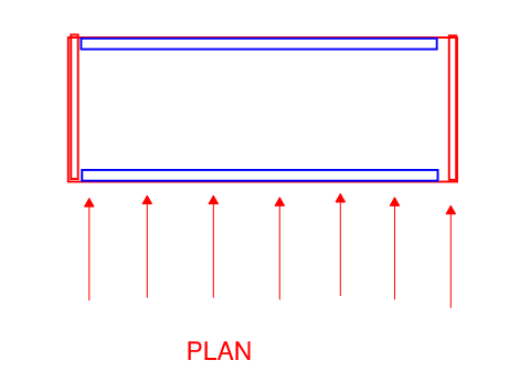
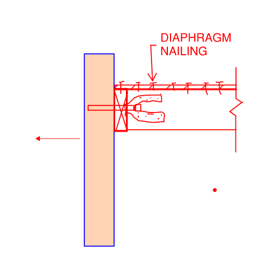
However, I am doing a job now where we have concrete walls supporting a wood diaphragm. This means that you've got mass concentrated at one spot - where the concrete wall is. I suppose you could think of it as a line load on the diaphragm rather than a typical area load. My question is: how do we reconcile this? The only way I can see this load getting distributed throughout the diaphragm is if it is transfered via tension or compression (depending in which direction the building is shaking) through the plywood. But none of the literature I've read ever mentions designing diaphragms for tension/compression. This leads me to believe that I must be thinking about this incorrectly.
By the way, I suppose this scenario would be analogous to a typical wind load situation. You've got wind hitting the walls around the perimeter of the building. These walls transfer wind load into edges of the supporting diaphragm. Now how does that load get distributed throughout the depth of the diaphragm? Again, I can't see any way other than tension/compression in the plywood, but I've never heard of anyone designing plywood for that. I suppose it's kind of funny how seismic analysis actually makes more sense to me than wind analysis, but I guess that's because it's the soup I swim in. Thanks for any help.