Continue to Site

Eng-Tips is the largest engineering community on the Internet

Intelligent Work Forums for Engineering Professionals

  • Congratulations IDS on being selected by the Eng-Tips community for having the most helpful posts in the forums last week. Way to Go!

Wood roof purlins with roll blocking on steep glulam trusses: is friction component allowed to resist sliding?

thejonster

Structural
Feb 8, 2011
69
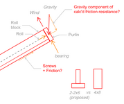
With wood purlins, I'm discovering that I have to resist rolling, this due to the lateral component of the purlin reaction on a sloped roof and the distance from the centroid of the purlin to the bearing point. This is significant because the reaction force, normally taken in bearing is large compared to what I can use to resist it.

Normally "Compression perpendicular to grain" (Fc⫠) is used for wood connections in bearing (~3.3k per 2x6 area), but on a 6:12 sloped truss, I have to use nails or screws to 'bear' the reaction against sliding (only ~110 to 170lb per toe screw depending on Cd of load case), you can see how this would add up. I'm using screws because nails are so terrible in withdrawal, and uplift is a factor. I usually see flat purlins for this reason, but I'm using upright purlins because customer requires 10' spacing for some nice glulam trusses.

My main question: (if TL;DR)
  • is wood to wood friction component allowed in calculation to reduce the amount of screws needed to resist sliding down the truss? A search of the NDS for 'friction' returns nothing. This is a large roof the saving would be huge, reducing screws needed by half (adding up to thousands on this roof).
Follow up questions: in order of importance, 1 & 2 most important
  1. Does anyone else have a better way of doing this? This is my first attempt at this problem, and using 4x6 purlins would mean almost 2x overall greater wood mass, or using a steel angle w/ 2x8 requires L8x__x1/4" and some prying calcs. Or does Simpson make a product for purlin roll & sliding?
  2. Does edge nailing of downhill purlin allow for this to act as a unit, and allow for an 'every-other' pattern for roll blocking? Sheathing not shown for clarity.
  3. Please confirm? I believe it's appropriate to use the full bearing component of gravity load for the friction calculation. Even when lubricated, wood-wood has a .20 coeff of friction. re: https://www.engineersedge.com/coeffients_of_friction.htm .. I'd rather use a value published from AWS, but sadly did not find.
  4. I think I've answered this question, but: customer proposed 2x6 assembly, but I think 4x8 best: making an assembly requires more nails and labor (and calcs), and leaves a 1/2" gap at top, doesn't save much wood.
  5. Bonus: Use 20' purlins and stagger layout?
  6. Also: NDS 2018 11.3.1 says wood screws are subject to toe-nail factor in shear and withdrawal.. so I'm detailing a toe 'nailed' wood screw and using the .83 & .67 Ctn factors respectively. I just think it's oddly named for screws & bolts, first time realizing it applies to those.

1744126938788.png1744128072465.png
 

Attachments

  • 1744127907269.png
    1744127907269.png
    22.7 KB · Views: 1
Last edited:
Replies continue below

Recommended for you

Working out the geometry for purlins across a slope is no fun. I do not frame like this often, but last time I did I had to sharpen the pencil a bit to work through all the geometry.

Here are a couple of thoughts
-I agree - No friction.
-For sloped roofs make sure you are considering the direction of all loads - remember that live loads act on a projected surface and can be modified for roof slope and member orientation. Dead loads should also be modified for slope.
Simpson HGA10 have some decent load values for loading across a member or along a member, if needed. These also work to resist uplift.
-The (12) #10 screws @ 4x blocking points to a fairly large load parallel-to-slope @ blocking transfer - Unless you have some very large snow loads this value seems high to me for a 6:12 roof
I have to resist rolling, this due to the lateral component of the purlin reaction
Where is your "lateral component of purlin reaction" coming from? If there is a weak-axis "reaction" then you must be resisting loads through weak-axis bending (bi-axial bending actually) of purlins. For a 2x spanning 10' this would not be much of a load and the weak-axis reaction should not be large. If you are not resisting in weak-axis bending, then there must be another mechanism carrying the load parallel to the roof slope. Possibly diaphragm action of the roof sheathing.
Either way the blocking along glulam members likely sees the load, but you might put some thought into load paths and how the weak-axis component of loading gets "out" of purlins and "in" to the glulam framing. Also consider how it is being resisted within the glulam component.
 
I don't really understand your issue? Are you worried about the purlins sliding down the truss top chord?
I would never account for friction in such a case.
Surely by the time you sort your uplift fixing it will resolve the sliding issue easily
 
I appreciate the feedback, it seems no for friction is the initial opinion.

As an analogy I was considering using a safety factor of 1.5 similar to soil sliding, so my μ used would be .25/1.5=.17, and since we use friction in other engineering cases and the NDS doesn't prohibit its use I considered it a way to save a good fraction of fasteners. The friction force is real, and that sliding resistance is only needed when the gravity load it's needed for (and that increase friction) are there. The same screws are used in withdrawal with the load cases where uplift occurs and there's no friction.

RWW: I wasn't clear, I meant the component from the purlin left after considering normal bearing force, the difference between vertical gravity loading and normal bearing, as well as the eccentricity between the centroid of the purlin and the center of bearing.
GACat: I can't use pure normal force bearing on the truss because of the truss slope, so I need to 'bear' on the screws as well perpendicular to the normal force, as shown in the free-body diagram (or my best attempt at one)
 
Last edited:
I appreciate the feedback, it seems no for friction is the initial opinion.

As an analogy I was considering using a safety factor of 1.5 similar to soil sliding, so my μ used would be .25/1.5=.17, and since we use friction in other engineering cases and the NDS doesn't prohibit its use I considered it a way to save a good fraction of fasteners. The friction force is real, and that sliding resistance is only needed when the gravity load it's needed for (and that increase friction) are there. The same screws are used in withdrawal with the load cases where uplift occurs and there's no friction.

RWW: I wasn't clear, I meant the component from the purlin left after considering normal bearing force, the difference between vertical gravity loading and normal bearing, as well as the eccentricity between the centroid of the purlin and the center of bearing.
GACat: I can't use pure normal force bearing on the truss because of the truss slope, so I need to 'bear' on the screws as well perpendicular to the normal force, as shown in the free-body diagram (or my best attempt at one)
No friction, regardless of the factor of safety. If you are in an area of significant seismic activity, the force creating that friction might be zero.
 
RWW: I wasn't clear, I meant the component from the purlin left after considering normal bearing force, the difference between vertical gravity loading and normal bearing, as well as the eccentricity between the centroid of the purlin and the center of bearing.
GACat: I can't use pure normal force bearing on the truss because of the truss slope, so I need to 'bear' on the screws as well perpendicular to the normal force, as shown in the free-body diagram (or my best attempt at one)

I still think you may want to revisit the overall statics a bit. Unless the purlin is carrying bi-axial bending (and it might be - but a 2x is not going to carry much in weak-axis) then the only reaction would be normal to the purlin. The load parallel to the weak axis of the purlin would need to be resisted in some other way, and that load transferred through the system in a definable way. The way I see it you have the following:

-Option 1 - Bi-axial bending of Purlin. Purlin would need to be checked against bi-axial bending and the reaction would need to resist both normal forces and the "downhill" forces you are showing. If this checks out I would recommend something like a Simpson HGA10 @ purlin to glulam along with the blocking connections as needed.

-Option 2 - Purlin only carries load in strong-axis bending and the component of the load parallel to the roof slope is resisted in another mechanism (common one would be diaphragm action of the sheathing. This load would need to be taken out of the diaphragm through blocking @ glulam and considered in the design of the glulam system.) In this case purlin reaction would only be normal force gravity and uplift. You might still consider something like Simpson HGA10 for uplift resistance and "bonus" lateral strength.

At the end of the day your design might not be too different with these two options, but I recommend having a theory about how the load is resisted and carrying that load all the way through the system.

Also, I still think your forces may be too high. Unless you have some really large loads you should not have approx 1300# in the weak component of your purlins (12-#10 screws). This would correspond to around a 3,000# reaction at purlins if I have done my napkin-statics right. That's a big reaction for 2x purlins @ 24" o.c.
 
Last edited:

Part and Inventory Search

Sponsor