Continue to Site

Eng-Tips is the largest engineering community on the Internet

Intelligent Work Forums for Engineering Professionals

  • Congratulations KootK on being selected by the Eng-Tips community for having the most helpful posts in the forums last week. Way to Go!

Wood shear wall compression chord 2

Status
Not open for further replies.

YoungGunner

Structural
Sep 8, 2020
98
I want to disagree with the Breyer's textbook about including distributed dead loads in the compression force in a chord for a shear wall. Points loads that the chord normally supports vertically yes, but not distributed loads across the entire wall. Here is why:

1. The SDPWS starts by using the same equation for the compression and tension in the chords. For the tension, the code specifically implies in 4.3.6.4.2 that the dead load may be used as a stabilizing moment to reduce the effect of tension. However, the code does not imply anywhere that an increase in the chord forces from that same dead load is required. I assume then, that theory of adding the load to the compression force came from the idea of "well, it was subtracted from the uplift."
2. It makes sense to me that a distributed load would help prevent an entire wall from lifting up on one end. I don't picture the distributed load assisting as if the wall is spanning chord to chord, but that the dead load over each portion of wall provides some resistance to it's own sphere, which ultimately prevents the whole wall from lifting (assume the dead load is enough to prevent uplift). However, to say that these vertical forces are amplifying the chord forces would imply that the wall has to span chord to chord - but the wall is much too flimsy to do that. The vertical distributed dead load remains supported by the distributed series of studs and headers, so it feels unnecessary that the chords would suddenly experience that force as if the studs weren't present.

Anyone want to provide additional insight?
 
Replies continue below

Recommended for you

I've spent much time considering these same issues in the past. I've landed on something like what you are describing:
- Tension/compression chords should be designed per the SPDWS equation. I consider that to be the post itself. Based on the way the equation reads, I don't know that the code is exactly clear on what is required, but a conservative approach would be to include vertical loads when they add to the compression post, and neglect them when they remove load from the tension post.
- The resisting dead load on the wall can be used to resist overturning. This is particularly beneficial for your holdown anchors.
- I agree that the uniform load would not be added to the end posts. You could maybe justify the trib from the end of the last stud bay (8" if the studs are spaced at 16"), but the remainder of the uniform load would just load the typical layout studs, not distribute to the end posts.
- Agree that concentrated loads on the end posts would be included as they load those posts directly.

Ultimately, I've found that there are a lot of different ways to approach this. I know some engineers that feel the wall is stiff enough that the uniform loads would distribute to the end posts and others that follow my line of thinking. I think either option can be justified as long as some rational judgment is used.
 
If you do the statics on a shear wall, and use the dead load on the wall to help resist overturning, then the compression end of the wall will have additional axial load.

DaveAtkins
 
Do a search - this topic has been debated before. I posted a sketch a while back. Didn't see it right away, and it's on my old computer, so I can't share it again here.

Run through the statics on a simplified shear wall - 8ft tall and 12ft wide. Break it into 3 discreet panels of 4x8. Look at it without dead load and then look at with dead load. Look at how the shear transfers between panels and the influence of the dead load on each individual panel in the wall. Essentially, a wood shear wall isn't a single, flexible unit. It's a series of fairly rigid, interconnected units. So the dead load acts on each unit and reduces overturning, and thereby reduces the uplift load it transfers to the next panel as it works its way back to the end of the wall and the final uplift connection.
 
phamENG - appreciate your feedback, but the question isn't about uplift but on whether we should include the dead load on the compression chords. I have searched before posting and there were no conclusions on whether dead loads should be applied to the chord. Much has been said about uplift, but not compression.

DaveAtkins - statics on the wall tells me that the studs in a wall support distributed loads, period. If I've designed the hold-down at the end of the wall to prevent uplift, then there is no reason to assume the distributed load across the wall would build up to be a singular point load in that compression chord. The studs support the distributed load already - why does the chord need to be designed for it as well?

I do appreciate the comments but I need a clear explanation to understand, so my challenging is just to provoke clearer responses.
 
I agree that IF you are not counting on the dead load to resist overturning, then the dead load stays in the studs throughout the wall. This is a tried and true way of designing a shear wall. But if you try to take advantage of the dead load on the wall to reduce the tension in the holddown, then the compression force at the other end of the wall increases.

DaveAtkins
 
I'd tend to agree with DaveAtkins. If you want to rely on the dead load of the entire wall to lower the tension load for your hold down, then you must assume that the compression post gains load from the UDL as well. The tension and compression posting form one large couple for overturning.
 
The distributed vertical forces stays in the studs always. The freebody diagram we use for shearwalls traditionally does not account for any support at the stud interval. I think the best free body diagram would include compression only supports at the field studs, and a T/C supports at the shear wall chords. This model would capture both the reducing effect of the vertical loads on chord tensions, and it would more correctly determine the compression chord force including dead loads.

To make it simple we could just use the traditional model and for the DL/LL terms just use the actual tributary loads to that compression chord.
 
DaveAtkins & EngDM - I still don't see why that would be the case. I know what you're saying, it's been preached to me before, but it doesn't make sense why.

Regarding uplift, in order for the wall to lift up it has to push against the floor or roof system which naturally pushes back against it with gravity and uplift overall is reduced. It makes sense to me that the distributed load at the center of the wall is pushing down on that wall and thereby impacts the uplift at the end of the wall. The only thing protecting this wall (theoretically) is the hold-down at the end - it has no other anchorage to help resist.

Now looking at the compression - in a wall system, the compression chord at the end of the wall is the only thing resisting the compression caused by the original lateral force. But the dead load across the wall was originally supported by the plethora of studs. Why would we now assume that the wall "spans" from uplift side to compression side and that the compression side has to now resist all that vertical dead load in addition to the lateral force? I don't even see a load path for how the distributed load at the center of the wall impacts the chord at the end, unless the wall was designed to "span".
 
YoungGunner said:
statics on the wall tells me that the studs in a wall support distributed loads, period. If I've designed the hold-down at the end of the wall to prevent uplift, then there is no reason to assume the distributed load across the wall would build up to be a singular point load in that compression chord. The studs support the distributed load already - why does the chord need to be designed for it as well?

One of the challenges with wood design, in general, is that these assemblies behave very different in reality than the way we traditionally analyze them. Is all of the "moment" in the wall really composed of a compression / tension force couple in the chords? Heck no! It's just conservative and convenient for us to analyze it this way.

When deviating from these traditional and conservative assumptions, I tend towards caution. So, on a personal level, I would probably design the compression chord for some tributary compression from the rest of the wall. 50% of the line load seems like it might be too conservative though. I'm fine with that extra conservatism for new construction.

That being said, if I'm really trying to get an existing wall to work, then I might do what you suggest and use only the share of the trib area for one stud, maybe two. The question you have to ask yourself, however, is whether you're comfortable with a level of conservatism that is lower than most design.
 
Ahhhh...I see. Sorry I misunderstood the original question.

As Josh said, this comes down to limitations of practical wood design. Unlike a steel braced frame where we have a few discreet members to track loads through, we have a whole lot of interconnected studs and sheathing and anchorages that, in reality, all work together to resist the loads. But to analyze it in a really meaningful way is nigh impossible. So we simplify it. But even as we simplify it, all of our assumptions/simplifications have to work together within the confines of static equilibrium and other basic principles of engineering mechanics.

Consider a shear wall with no lateral load, only dead load. It has a uniform compressive load across the top of the wall, and a uniform compressive force across the bottom of the wall opposing it (or you can say there's a series of point loads at 16" o/c - either way). It's in equilibrium.

Now apply a lateral load to the wall. That lateral load will be resisted by the sheathing, so it creates a tension and compression couple at each chord. Now we have a choice - we can assume the wall is stiff in bending or we can assume it's flexible in bending. If flexible, then the dead load stays in the individual studs, and the shear load stays in the sheathing and is delivered to the end studs for tension and compression regardless of our lateral load. If we assume it's stiff (rigid, really), then it's different. As we increase our lateral load, the wall is going to try to rotate around some point. It's generally convenient to pick the opposite corner, but it's equilibrium - any point will do.

So in this rigid assumption, the wall will rotate, which means we end up with some non-zero displacement at the base of the tension chord. If the wall is rigid, then that means there is a non-zero displacement everywhere along the base of the wall until you get to the compression chord. If we're assuming that, then the dead load is no longer being resisted by the individual studs, but is now being carried by the sheathing. That means it works its way back to the compression chord and has to be resisted there.

So....you have to make a choice. Assume the wall is not rigid and ignore the dead load that is not directly tributary to the tension and compression chords, or assume that it is stiff and the tension and compression chords have to be designed for the sum total of the 0.6D+0.6W overturning moment.

In reality, it's somewhere in between. The dead load isn't going away (we hope!) and will help even with a flexible wall. The studs also aren't really being picked up, so the dead load isn't really all being dumped into the compression chord. BUT...good luck showing all of that in a comprehensive calculation that stays in budget. There is a limit to the achievable accuracy of our designs, and any attempts to approach it tend to do so asymptotically. The methods described in the SDPWS and Breyer's book are essentially the point at which the structural engineering community have decided that trying to improve it any more will only increase our costs while not providing a noticeably less expensive or more reliable design.
 
Thanks phamENG for your detailed response. True that this discussion about chords is merely the difference between an extra stud most of the time, but we live in an area where builders have literally scolded us for specifying an extra ply header over competitors and such. So I'm really looking into what nuances could be made to our calcs to reduce cost anywhere without jeopardizing the integrity of the structures. Given me things to think about though, appreciate it.
 
No problem. Hope it helps.

I don't practice in Utah, so I don't know, but I've had similar run-ins here. I've found that there are usually 2 general mindsets of contractors: 1) the structural engineer is an annoyance to be avoided when possible and beaten into submission when necessary and 2) the structural engineer provides a valuable service and helps the project. Once I find a contractor is in the 1st group, I resist them through the end of the project and then don't work with them again. If they show up on a design-bid-build project in the future, they know I'm not going to be pushed around. If they're in the second group, I cultivate the relationship and have a few long term contractor clients now that I work well with. (Note the word "few" there...residential contractors are usually the worst.)
 
Muahahahahahah!

(Just kidding...your profile shows the state from which your IP originates)
 
YoungGunner said:
However, to say that these vertical forces are amplifying the chord forces would imply that the wall has to span chord to chord - but the wall is much too flimsy to do that.

That, all day long. I'd just say it a little differently.

1) I don't believe that the compression chord will see the dead load associated with the gravity loads applied to the non-chord studs.

2) The flip side of #1 is that I also don't believe that the dead load associated with gravity loads should be used to resist shear wall overturning. This will tend to offset any economic gains made at the compression chords.

3) Fundamentally, I feel that any attempt to consider wood shear walls rigid is flawed and fails to recognize the true nature of a material that is "shear weak" and based on racking behavior, as a multi-panel wood sheathed shear walls tend to be.

pham's sketch and a bunch of other good information on the subject can be found here: Link.

YoungGunner said:
Much has been said about uplift, but not compression.

It's just a different aspect of the same conversation and the same theory. Much have what has been said about uplift applies to the compression chord situation which is, in reality, just the other side of the same fundamental behavior coin.
 
I typically leave it out of the tension side unless I'm on the cusp of a design change (going up a hold down, or the deflection needs to come down). Consequently, I have not included it on the compression chord but I usually observe that the chord has more reserve capacity than the hold down (may not be applicable for multi-storey).

How would I handle it in the compression chord?
1. Direct all the compression in the chord and add a ply if it needed it. Probably applicable for a higher aspect ratio wall where the 2:1 slope tends to hit the chord.
2. Ignore the load if it is distributed across a wall with A.R. < 1
 
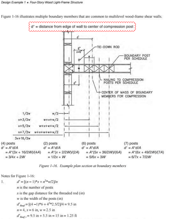
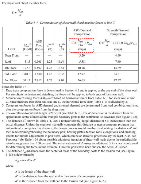
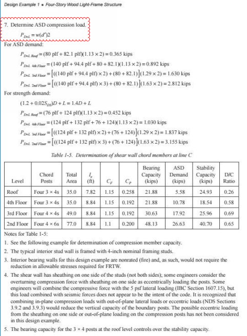
See this example in 2018 IBC SEAOC Structural/Seismic Design Manual. Basically just (Overturning moment / moment arm) + Uniform load * 1/2 stud bay for hold-down case.

1QHT8hQ_ku45q7.png

TmWT409_f2rkbk.png

tQzcRZi_cyx3kz.png
 
Yes and the next part of the example uses the distributed load as a resisting moment for tension calculations. This example seems to also indicate that using the full width of the wall load as a moment dumped into the compression chord is not necessary. But at KootK's behest, they are using it for reduction of tension forces in chord.

Does anyone know of any test data that measure the actual hold down force on a wood shear wall with gravity loads? Since this topic came up I have been picking around looking but I don't have fancy library subs anymore so I can't view much of what I am finding :(
 
I stand by what I said. If your are using ALL of the dead load on the wall to resist overturning, then the bottom of the wall is lifting off the foundation and you cannot count on the dead load staying in the studs and going into the foundation below. You must add compression to one end of the wall which is equal to the tension you are subtracting from the opposite end of the wall. It's static equilibrium.

DaveAtkins
 
Status
Not open for further replies.

Part and Inventory Search

Sponsor