Continue to Site

Eng-Tips is the largest engineering community on the Internet

Intelligent Work Forums for Engineering Professionals

  • Congratulations KootK on being selected by the Eng-Tips community for having the most helpful posts in the forums last week. Way to Go!

Wood Shearwall, Steel Boundary Elements

Status
Not open for further replies.

T_Bat

Structural
Jan 9, 2017
213
Hey all,

I have a single story building with an interesting entry tower. There is clerestory glass and ground to roof glass for two of the exterior walls. My plan was to provide steel framing in this area. This is about 24 feet tall and the architect is hoping for some relatively small columns. Typically, I would provide moment frames but in order to minimize any potentially large HSS columns, I'm thinking about providing shear walls instead. Due to the clerestory glass I cant have the wall continue to the roof. I'll need a steel girt to support the head of the wood wall so I'm thinking about typing it to the top of the wall for in plane shear transfer. One side of the wall will also tie into the steel columns which I will connect for uplift.

Basically I have steel drag strut on top of my wood wall and then one of my shearwall endposts is a steel column. The base plate of the column will be designed for uplift and basically becomes my holddown. I've attached a rough sketch for reference. I'm still just looking schematically here so I'm just looking to see what holes there are in this approach. Any comments or critiques are welcome.

As an aside the walls here will be framed by 2x10's so any additional comments about using 2x10 for studs in a shearwall are welcome.
 
 https://files.engineering.com/getfile.aspx?folder=e1fb4795-63e0-4740-90bc-347dff3ea48a&file=Scan_Sep_25,_18.pdf
Replies continue below

Recommended for you

I know Simpson has a line of shearwalls that are a hybrid between steel and wood. Your wall will be much bigger but you might get some ideas from their literature and white papers. If I recall the main issue is minimizing initial set or deflection under load in order to meet whatever deflection criteria you need for the glass. The actual calculated load deflection doesn't mean much if you deflect an inch or two at initial load set. Again, just from memory, this requires tight construction tolerances and perhaps the use of construction glues and self tapping screws rather than common nails to increase stiffness. I also recall that much of the design is governed by wood crushing so you might need to think about wood grades and strategic location of steel. It sounds like you will have steel at the high stress locations anyway.

If you have serious trouble meeting deflection criteria you might consider cable x-bracing and turnbuckles where the wood is mainly a space filler.
 
CAB - thanks for the info. I've used the simpson walls before. For this project they will be cost prohibitive. Those are generally for walls where you just can't get the aspect ratio's you need. I should be fine from that standpoint. This will really be a pretty normal shearwall except the steel on top on the one steel chord member... I think haha.
 
I've used a wood shearwall with a steel column as a boundary element a number of ties. You seem to have a handle on the issues in play.

The only other issue I would ask - is this for seismic loads too? Because for your clerestory portion, I would define those steel columns as cantilever columns, which means a low R that you have to carry all the way through the design. Still likely works and is more efficient than a frame, but should be taken into consideration.
 
If that steel can act as a t/c member of equal or greater capacity than a top plate it should work. You may even want to drop the steel slightly and place a 1-2 ply 2x nailer to the top of the girt, this is for sheathing attachment. then it is no different from the view of the sheathing? Simpson makes some screws for wood to steel. I wouldn't relay on sheathing to steel fasteners without more research.

How are you attaching the top of wall to the roof dia?
 
I should note we usually detail it as Eric describes - double 2x or possibly a single 3x vertical member that we count on for the sheathing attachment, then use welded threaded studs or the Simpson screws he mentions for attachment to the steel column. If the sheathing continues over the steel column, it's mostly for cosmetic purposes and I don't like relying on the connection there as the load path.
 
My plan was to have nailers on bottom (possibly on top) depending on the arch requirements. The walls are not “attached” to the roof diaphragm. The roof framing sits on steel beams at the tops of the columns. The columns will carry the lateral from the roof down to my girt at the head of the wall.
 
Hey guys and gals,

Just as I'm wrapping up my design the contractor is freaking out about my steel on this tower feature (see original markup). I'm looking into eliminating all the steel I can. After talking with the architect, I was going to try to hide some wood posts in the mullions of the clerestory glass that go from ground to roof. These posts would be buried in my shear wall the "cantilever" up to grab the roof. This cuts down my roof beams span so I can get LVL's to work. However when I starting looking at how this would work for my shear walls I got a little wild... If I were doing things totally by hand (or excel) I would:

1. Calculate the shear to this "wall" based on tributary width.
2. Divide this shear as a point load between my columns.
3. Check if my PSL works for the cantilevered portion by checking a short section fixed at the bottom.
4. design my straps across the PSL's for accumulating shear in each section.
5. sheathing, holddowns, foundation, etc.

However, I've been wanting to mess around with RISA's wood design so I buily the whole tower as a model (partly to see where I need to drag shear into the rest of the building). I got some very stout shearwalls and a few columns fail (in RISA). The shear my walls are seeing is very large. The hand calculated wind load (unfactored) is about 10-12 kips. My wall is about 22' long so the shear should be around 540 plf - RISA shows about 1000 plf. Obviously, this isn't intuitive and I can't figure it our on the back of a napkin so I'm seeing if this entire exercise is a waste of my time. I like to try to make my clients happy but is this a case of trying to reinvent the wheel?

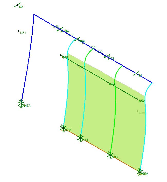
I suspect the added shear has something to do with the column elements in the model trying to rotate inside of the shearwall (It seems likely based on the deflected shape below)
Capture_mzwkej.jpg


Now that I've seen this... I can't unsee it. Although I don't necessarily think all model results are gospel but there may be something to this. The real PSL's will want to rotate in the shear wall and will need to be restrained by the nailing. All that to say I no longer feel comfortable with trying to make this work... even by hand. It seems step #3 from above would be overly simplistic for this real life situation. Am I missing something here? Back to steel?
 
Are you letting RISA determine your shearwall specifications, or are you hard specifying the wall type?

I ask because if the lateral sway can accommodate it, perhaps a lower wall stiffness would result in a less drastic cantilever action by the steel columns and possibly bring down the wall shears. Or perhaps, like often before, I'm talking out of my ass.
 
I was letting RISA do it for me. I don't disagree - the lower stiffness would possibly help things. But would I be artificially tweaking the model to get a result I want? We engineer do this all the time I know and as long as detailing/load path are consistent these things are usually fine. My bigger concern is that I asking these column to deliver all their shear at the top plate then remain rigid (or keep compatible deformations) with the wall. I'm not sure that's a reasonable expectation...
 
I don't necessarily disagree with you, but I also feel that with appropriate sheathing connections to the steel column and wall blocking, you should see similar enough deformations.
 
T_Bat said:
Now that I've seen this... I can't unsee it.

Ditto. As annoying as this surely is for your problem solving effort, it's also one of those glorious moments that I love to see where FEM helps to elucidate true behavior rather than stifle intuition.

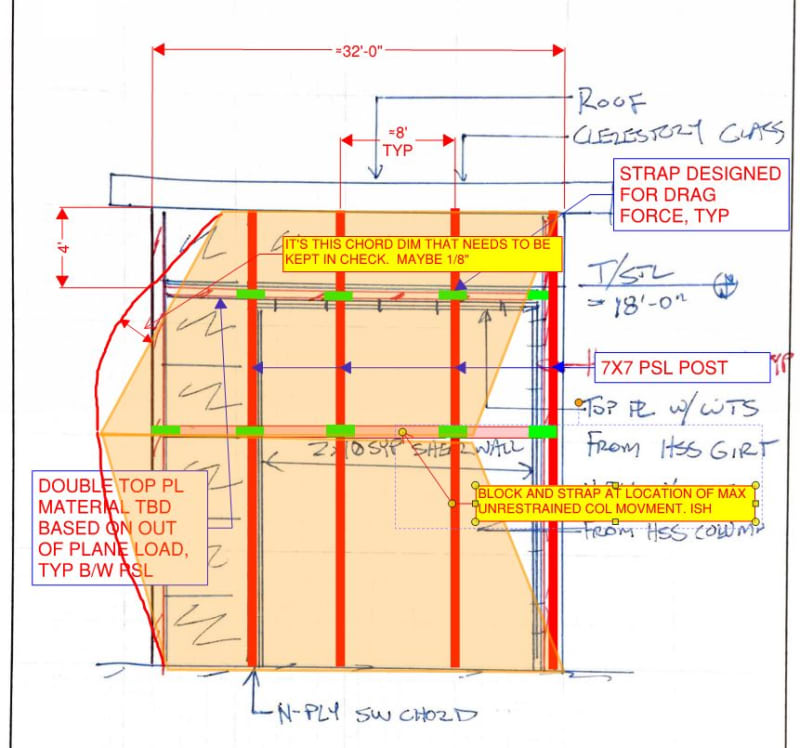
See my proposal below. I believe that this ties in with jayrod's overarching concept as I understand it to be: there's some value of differential movement for which this surely is acceptable. By enforcing some hard compatibility restraint strategically, you should should be able to cut the differential down dramatically. Of course, this isn't free either.

c01_beympl.jpg
 
Thanks for the info guys. I see what you both mean. I'm also seeing if I can lay a multi-ply LVL turned 90 degrees to act as a girt the catch the top of the wall. I'd make the corner columns steel and see if I can transfer the lateral load (as shear in the steel columns) to the girt. Then from the girt to the wall below. If I can make the girt work for OOP wind then I have one, solid collector and eliminate the need for additional detailing to ensure compatibility of the columns in the wall.
 
Status
Not open for further replies.

Part and Inventory Search

Sponsor