Eng-Tips is the largest engineering community on the Internet

Intelligent Work Forums for Engineering Professionals

Wood Truss Moment Frame

Status
Not open for further replies.

TRAK.Structural

Structural
Dec 27, 2023
88
0
0
US
Hi All,

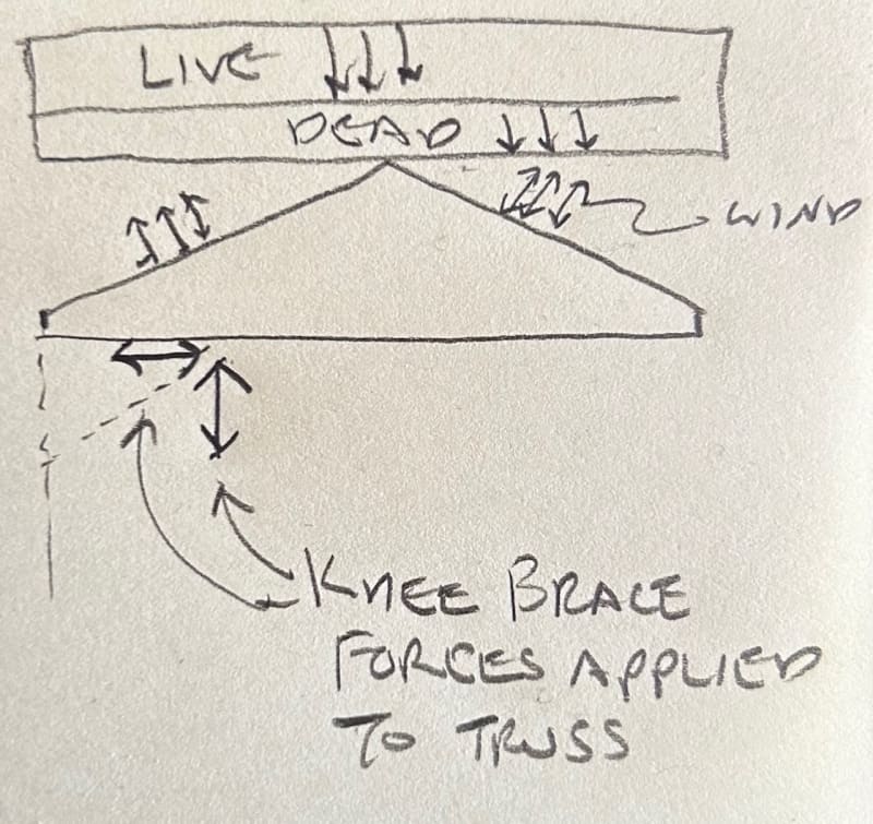
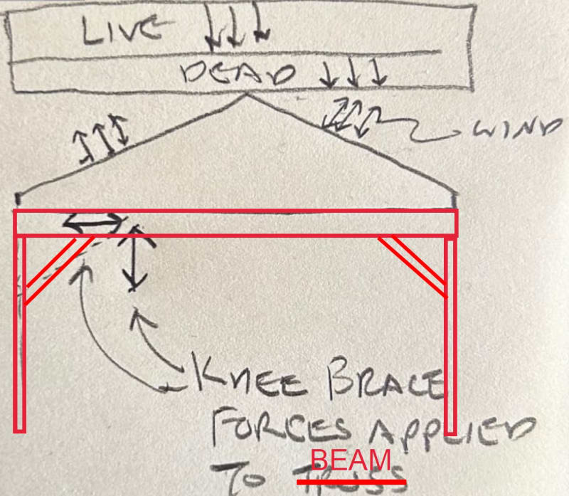
Working on an open pavilion/gazebo type project and need some opinions on a potential option I am considering for a lateral system. Generally the structure will be 30' x 24' in plan and approximately 9' clear height to the underside of perimeter beams and framed with treated wood post and beams. The roof is a simple gable with the ridge parallel to the 30' dimension. No heavy timber detailing with tenons, dowels, etc. just metal connectors, and fasteners. The client wants a clear-span throughout the central area under the structure (24' span) so we have agreed on using wood roof trusses to make this span. Considering lateral loads perpendicular to the ridge, I can use knee-frames at the two ends of the structure with a column that splits the 24' dimension. However, in the center of the structure (where I can't have any interior cols) I am finding that cantilever columns don't provide enough drift control for my comfort. I am considering trying to specify wood trusses aligning with the columns that would be connected to a knee brace and create a truss "moment frame" (see attached).

1. Is this a bad idea in general? Are there any major pitfalls or known issues with this approach?
2. Will a truss supplier/engineer even be able/willing to go along with this and design to provide the required resistance at the ends to create the "moment frame"
3. Any ideas on a simple yet reasonable way to estimate the required force couple at the col-truss connection?

Open to other ideas on lateral systems for loading in this direction. Post base connectors providing enough moment resistance is another issue that has led me to where I am; I have seen the Simpson and Sturdi-Wall products but the capacities and rotational stiffnesses are not great.
 
 https://files.engineering.com/getfile.aspx?folder=74b2e209-4bdf-4a85-9228-0e5550e31f9f&file=Screenshot_2023-12-27_200744.png
Replies continue below

Recommended for you

The building is fairly small. Are you planning to use factory fabricated trusses spanning the 24' dimension... gives you 24' clear space underneath. That's likely the least costly. The roof can act as a diaphragm transferring the load to the exterior walls. For the size, lateral loads should not be an issue. My error...it's open, like a gazebo. You can use engineered timber with metal connections (glulam rivets) for the moment from the frame or consider using knee braces at the corners.

-----*****-----
So strange to see the singularity approaching while the entire planet is rapidly turning into a hellscape. -John Coates

-Dik
 
Dik,

Yes, planning to use pre-fabricated trusses, designed by the supplier. Lateral loads are small yes, but a 30' diaphragm span to either end of the structure seems a little far to me. Diaphragm shear strength would likely work for the roof sheathing, and knee frames at each end of the structure are also probably ok but I still think drift may be an issue at the center of the structure.
 
I would design the corner posts as pinned, likely... I don't like embedded posts and design the connection plates, likely using glulam rivets for moment and use psl lumber. Load transfer shouldn't be difficult... don't know about seismic...

-----*****-----
So strange to see the singularity approaching while the entire planet is rapidly turning into a hellscape. -John Coates

-Dik
 
I've got enough cols around the perimeter that I think conventional sawn lumber beams and cols should work. My col spacing under beams that support the trusses is 8' ish, and at the gable end beams that carry only self weight its 12' spacing. Currently I've sized 8x8 cols and 4x12 beams, treated SYP.

Not sure I understand what you mean about designing connection plates for moment. If I'm using knee frames I don't think there is any moment to resolve at beam/col or knee/col connections.

I haven't checked numbers yet, but in my area I see through bolts for these connections most often. Are there any resources that illustrate the required checks at these through bolted joints? I'm most interested in accounting for loss of the wood member section due to the drilled holes since I don't deal with this condition often.
 
Using knee braces or moment connections... just an alternative. I've reviewed many century timberframed barns to know that knee braces with wooden pins work well <G>.

-----*****-----
So strange to see the singularity approaching while the entire planet is rapidly turning into a hellscape. -John Coates

-Dik
 
Question for you TRAK.Structural:
You show in the notes that you are delegating the design of the trusses to the truss manufacturer....makes sense and is done all the time.
But you are also imposing on these trusses significant end moments (dead, live, snow, wind, etc.) via the knee braces.

With this in mind don't you need to provide the truss manufacturer the imposed loads on their delegated-design-trusses?
Maybe you were already going to do this but your note C implies you are only providing them with generic gravity loads.

I would be very reluctant to require them to independently produce these imposed truss loads on their own.


Thanks JAE... I didn't realise he was using the trusses for anything other than 'sticks', framing across the outer beams. If requiring a moment at the ends of the trusses, I generally just stipulate the moment required. Truss manufacturer's software (at least in these environs) accommodates moments, easily.


They don't have to have a moment connection at the reactions, unless I'm missing something. Knee braces are only between columns and perimeter beams, I think.


I usually find glulam rivets to be better and less costly than through bolts. You have to be careful when placing through bolts that any shrinkage between the bolts does not cause restraint and crack the timber longitudinally.

-----*****-----
So strange to see the singularity approaching while the entire planet is rapidly turning into a hellscape. -John Coates

-Dik
 
JAE

Yes, delegated design trusses. Yes, I will have to provide end moments for the truss engineer. Was just trying to vet my approach before getting in to the weeds and progressing the design. I've never asked a truss supplier to do this and for a small project I am not sure how big of an ask this is. Ultimately I want the trusses and the lateral system to be designed and implemented as intended, any thoughts on whether or not trying to use a central frame truss will realistically translate to the final product?

See attached for the proposed roof plan utilizing the trusses for frame action at the center of the structure. My thought is to sandwich the knee brace btwn (2) closely spaced trusses (see attachment from original post). For calculating the end moments for the truss design I am considering just computing the horizontal component of the knee force and mutiplying by the vertical distance between the knee/col workpoint and the center of the truss chord that rests on the perimeter beam (doing this for all the applicable cases: D, Lr, W, etc.). Does this sound reasonable? I dont want to model a full truss, just using a stiff beam and the knee brace to get loads to my beams/cols in my structural model.

 
 https://files.engineering.com/getfile.aspx?folder=ed51d0f7-4d46-4738-99de-f729abb64c19&file=Screenshot_2023-12-28_142853.png
any thoughts on whether or not trying to use a central frame truss will realistically translate to the final product?
I think if you provide the truss manufacturer with a side elevation of the basic truss with the "frame" imposed loads on it you would stand a good chance of having the truss designed properly.

I'd want to call a couple of local truss manufacturers to discuss and share the load concept with them.
Something like this perhaps (very rough - there'd be another knee on the other side of course):
Truss_iogntg.jpg
 
This looks like an interesting challenge to me.

As others have said, you'd have to provide the forces, locations, and direction. It's definitely doable.

Although I'm wondering what that would do to the truss with gravity loads. As the truss deflected under live loads some of the force would be transferred through the knee braces.

If you wanted the truss designed for a lot of different wind cases the design could get pretty cumbersome.
 
This framing is more common in these environs. It avoids transferring the loads through the beam to the end truss and having two different types of trusses. The trusses in the 'gable' area will be heavier to accommodate the cumulative lateral loads.

Clipboard01_a0splc.jpg


-----*****-----
So strange to see the singularity approaching while the entire planet is rapidly turning into a hellscape. -John Coates

-Dik
 
if you google "large picnic shelter" images there are a lot of examples from relatively simple to elegant (even curved laminated arches); doesn't seem all that complicated or needing a complicated truss.
 
The devil is in the details with knee-brace type construction. Make sure you are considering all failure modes of the members and fasteners - including local stability. How much deflection are you getting just considering flag-poled columns?
 
I've decided against using the center truss as part of my lateral system, just too much to coordinate with the supplier.

Now on to the connection designs.

Dik - you mentioned timber rivets in a previous reply, are these applicable to sawn lumber or only glue laminated wood products?? Chapter 14 of the NDS wood seem to indicate only for glulam....
 
...for lumber Species as shown from the Canadian wood code CSA O86:

Clipboard01_yztpnj.jpg


-----*****-----
So strange to see the singularity approaching while the entire planet is rapidly turning into a hellscape. -John Coates

-Dik
 
Curious if anyone else has used the approach as dik noted above. Using the Canadian reduction factors for timber rivets in sawn lumber for structures in the U.S.
 
Status
Not open for further replies.
Back
Top