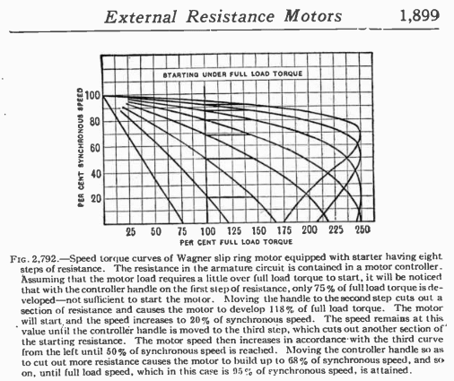
Does the added resistance in these motors on start up improve power factor. And also how is the inrush current limited I know that the as the rotors EMF passes the motor windings a counter EMF is produced decreasing the line current but how is inrush current different in these compared to squirrel cage motors?
Navigation
Install the app
How to install the app on iOS
Follow along with the video below to see how to install our site as a web app on your home screen.
Note: This feature may not be available in some browsers.
More options
Style variation
-
Congratulations MintJulep on being selected by the Eng-Tips community for having the most helpful posts in the forums last week. Way to Go!
You are using an out of date browser. It may not display this or other websites correctly.
You should upgrade or use an alternative browser.
You should upgrade or use an alternative browser.
Wound rotor motors
- Thread starter Jk1996
- Start date
- Status
- Not open for further replies.
Power factor will be better, on start up, but motors spend so little time spinning up it will not matter.
This fig does shows steady state torque. Inrush depends on the resistance inserted. Inrush will be approximately proportional to percent full loss torque at zero speed.
This fig does shows steady state torque. Inrush depends on the resistance inserted. Inrush will be approximately proportional to percent full loss torque at zero speed.
Audel's ELECTRIC LIBRARY said:
Aren't Audel's books fantastic? One does have to use liberal quantities of salt when assessing the legitimacy and description of electrical medical devices, but other than that . . .
CR
"As iron sharpens iron, so one person sharpens another." [Proverbs 27:17, NIV]
CR
"As iron sharpens iron, so one person sharpens another." [Proverbs 27:17, NIV]
jK1996: In the big scheme of things developed torque (at any speed point) is dependent on the applied voltage, the current flowing in the winding, the power factor at that particular speed point, the resistance of the winding(s) involved, and how far away from synchronism the specific speed point is (i.e, the slip).
If the contacts close simultaneously
(Torque) = (Tlockrotor) + (lock rotor current)*(rotor leakage reactance/(stator leakage reactance + rotor leakage reactance)) * (factor) + sin(2*pi*line hz*time)
where
(factor) = e^((-1)*(2*pi*line hz)*(Stator cct resistance)*(rotor cct resistance) / (magnetizing reactance * (stator cct resistance + rotor cct resistance)))*time
Note: calculated torque, lock rotor torque, lock rotor current, leakage and magnetizing reactance, and all resistances are in PER UNIT.
As any added resistance (e.g. a liquid rheostat or a switched resistor bank) in the rotor circuit becomes part of the rotor circuit during the start, it can be seen that the addition of resistance will have an effect on both the starting torque and the lock rotor current. More resistance in the circuit reduces inrush current (because there's only so much voltage to go around) and consequently the torque developed will also be less than a full-voltage condition.
Converting energy to motion for more than half a century
LionelHutz
Electrical
Gr8blu - are you trying to equate a wound rotor to a squirrel cage by saying what happens with a reduced applied voltage because your statement "the torque developed will also be less than a full-voltage condition" isn't making sense.
Torque doesn't go down, the breakdown peak just shifts around.
Torque doesn't go down, the breakdown peak just shifts around.
electricpete
Electrical
I don't know about the + sin(2*pi*line hz*time). I do indeed recall a line frequency component of torque based on interaction product of ac component of current with a decaying dc component of current.... but that product decays with the decaying dc component whereas your line frequency torque component is shown as if it would continue undiminished (assuming rotor were locked in position and hadn't tripped). I think your sin(2*pi*line hz*time) term should be multiplied by a decaying term, maybe by that middle term that includes factor.If the contacts close simultaneously
(Torque) = (Tlockrotor) + (lock rotor current)*(rotor leakage reactance/(stator leakage reactance + rotor leakage reactance)) * (factor) + sin(2*pi*line hz*time)
where
(factor) = e^((-1)*(2*pi*line hz)*(Stator cct resistance)*(rotor cct resistance) / (magnetizing reactance * (stator cct resistance + rotor cct resistance)))*time
=====================================
(2B)+(2B)' ?
- Status
- Not open for further replies.
Similar threads
- Replies
- 16
- Views
- 9K
- Locked
- Question
- Replies
- 11
- Views
- 5K
- Locked
- Question
- Replies
- 6
- Views
- 5K
- Locked
- Question
- Replies
- 12
- Views
- 1K
- Replies
- 8
- Views
- 11K

