Continue to Site

Eng-Tips is the largest engineering community on the Internet

Intelligent Work Forums for Engineering Professionals

  • Congratulations waross on being selected by the Eng-Tips community for having the most helpful posts in the forums last week. Way to Go!

Wye Wye Transformer Grounding/Bonding

Status
Not open for further replies.

NJWVUGrad

Electrical
Jul 17, 2015
7
We have a customer who has 480V solar array that is backfeeding a 120/208V building service via a 750KVA Dry-Type Grnd-Wye to Grnd-Wye step down transformer. This transformer has been provided with a grounded Delta tertiary winding

We have 4 wires (A,B,C,N,G) to the High side and Low side of each transformer – which land on the X0 and H0 bushing (respectively) on the transformer – the XO and H0 are not bonded together. The neutrals are not bonded to ground in transformer on either side. The Wye-Wye transformer configuration was requested by the utility.

The issue that we are having is that when energized and under no load (The breaker supplied from the 480V side of the transformer is open) the breaker feeding the low side of the transformer is showing a current reading of 120A per phase and 360A on the neutral.

We are trying to determine what is causing these currents, it appears to be a grounding/bonding issue. Does anyone any insight into what could be causing this circulating current and the proper bonding for the transformer.
 
 http://files.engineering.com/getfile.aspx?folder=720085ca-1fa4-4915-8ea0-462bd7b34fc4&file=Pages_from_SG3Y0750KB_Dwg_(002).jpg
Replies continue below

Recommended for you

Energized from the solar panel inverter? Have you looked at the waveform? The amp readings seem to point to a triplen harmonic. The delta tertiary will allow third harmonic current to flow in the wye winding even with nothing connected to the low side. If possible, try energizing from utility or generator source. Or check put a power sysstem analyzer on it to check harmonic levels. The nameplate shows the tertiary delta to be corner-grounded, BTW.

Who specified the transformer?
 
These readings were with the transformer energized from the low side - the 208V utility side. The solar is on the 480V side, but the breaker feeding that was open.

This was discovered while preparing to connect the PV array the grid.

 
This could still be harmonic related, depending on the types of load on the 208 V system. My suggestion is to find a way to measure the harmonics.
 
The full load current on 277 V side is 1563 A. So no-load current should be about 15-30A (please check the test report). Did you kept the unit for some time to stabilize the current? The one corner grounding cannot normally affect this. Please energise again after disconnecting this earth.Of course there is a circulating current inside the tertiary. Please check the ratio/resistance of tertiary winding(if all terminals are accessible) to rule out any fault inside tertiary.
 
Have you checked voltage balance? Perhaps a bad neutral? Might want to see if the current shifts when switching some single phase 120 V loads. I suspect you have some V0 driving this current. On the utility side, the 208 is likely fed by a wye-wye transformer with X0 and H0 bonded and grounded. I0 on the utility side may see your transformer as a grounding bank.
 
The transformer is acting as a grounding bank and is feeding unbalanced load current on the utility system. All of the current is zero-sequence, with the three phase currents having the same magnitude and angle, adding to three times in the neutral. Zero-sequence current is circulating in the delta winding. Most utility transformers of this size would be grd wye - grd wye with no delta tertiary. With no delta, it would not act as a grounding bank.
 
On what conditions this grounding bank action will happen?
When I was thinking about the cause of this problem, I met with a situation yesterday, almost identical to the one under discussion.
Three banks, identical, each of 750 MVA 400/220/33 kV is feeding an Aluminum smelter. When fourth bank is switched on from 400 kV side with 220 kV open, The currents were as below.
Current flowing through R, Y & B phases and also through neutral.(normal no-load current =0.29A Voltages are HV phase voltages.
IR – 44A, Angle: 37°
IY – 43A, Angle: 34°
IB – 48A, Angle: 36°
Neutral current – 137.8 A, Angle: 212°
VR – 224.58kV, Angle: 0°
VY – 235.33kV, Angle: 119.47°
VB – 234.88kV, Angle: 239.78°
If it is grounding bank issue there are 3 other parallel delta stabilizing tertiaries on the same bus.
 
A delta - grd wye connected transformer will act as a grounding bank and zero-sequence current will flow to unbalanced loads or ground faults on the grd wye side. A wye-delta-wye transformer with one of the wye windings disconnected will act as a delta-wye transformer. If both wye windings are connected, the transformer will still be a ground source, but the load through the wye windings may make the grd wye - delta ground source current insignificant.
 
On what situations in power system, such a need for grounding bank arise?
 
slight typo, jg
Delta-wye transformers are relatively trouble free.
It is the wye-delta transformers that act as a grounding transformer along with some other nasty effects.
I don't think that grounding will make a difference.
You may try breaking the delta if that is possible.
This looks like harmonics.
Unbalance on a wye delta will not be equal currents and the neutral current will be the residual, not three times.
Your neutrals are ungrounded so the issue is not with grounding.
Try looking at the wave forms with a scope.
Look at the building panel wave forms without the transformer connected as well.

Bill
--------------------
"Why not the best?"
Jimmy Carter
 
So what do you call the wye-wye transformer with delta tertiary and an open circuit 480 primary and back fed secondary? Whether you call it delta-wye or wye-delta makes little difference. The delta winding provides a path for zero sequence current to circulate.

If all you have is zero sequence current, the neutral current will be three times the phase current. The only source of positive sequence would be the small amount of magnetizing current, which would not show up on the neutral.

I agree that a scope waveform would be interesting to see. All three line currents in phase, with the neutral 3 times the magnitude and 180 degrees out.

The neutral is not bonded to ground at the transformer in question, but it will be at the 120/208 service transformer and again at the service entrance per code.

I can assure you that delta-wye transformers are a problem when the primary is opened. Consider two substations with delta-wye transformers feeding radial distribution load. It is desired to take one sub out of service, so the normally open distribution switches between them are closed, and the circuit switcher at sub A is opened. It is desired to keep the station service at sub A energized, so the distribution bus is back-fed. With no switch between the station service and the wye winding, this keeps the transformer energized without load. The sub A transformer now becomes a very good grounding bank for distribution unbalance. As I recall, unacceptably high neutral current and unbalanced voltages were the result until the substation A transformer wye side was isolated.

 
Hi Steven;
I am going by the convention that transformers are described as primary:secondary.
If the wye is energized, the wye is a primary and the delta is the secondary. Hence delta:wye
A delta:wye transformer has no problems until you back feed it and then it becomes a wye:delta and becomes a grounding bank.
I am sure that our misunderstanding is with the words used to describe and not in the basic understanding.

Bill
--------------------
"Why not the best?"
Jimmy Carter
 
Waross,

I am unfamiliar with the convention you speak of, and find it very problematic. What if the transformer is energized from both sides? I suppose you might consider power flow, but at pf less than unity, you'll find the direction changing with every cycle. Plus it leaves my substation A transformer above un-defined after disconnecting the lower voltage winding.

The convention I'm used to uses the voltage rating of the windings, with the higher one listed first.

Lingo aside, are we in agreement the OP's transformer is acting as a grounding bank?
 
Steven;
I respect your knowledge and experience in the electrical industry.
I also recognize your position as one of the lifetime top ten MVPs of this forum.
I note also that you have been recognized as a "Fellow" of Eng-Tips.
If we are in disagreement, please mark it up to my poor attempts to explain myself
Steven said:
Lingo aside, are we in agreement the OP's transformer is acting as a grounding bank?
Well yes and no.
A four wire wye:delta connection is more than just a grounding bank.
The four wire wye:delta (power fed from the wye side) is a great equalizer.
If the voltages are unequal it will attempt to correct them.
If the phase angles are unequal, it will attempt to correct them.
If one phase is lost it will attempt (sometimes successfully) to replace it.
As for grounding, if one phase goes to ground, the voltages will be unequal and the wye:delta will try to correct the voltage.
The wye:delta has the ability to transfer power from one phase to another phase.
While the grounded wye:delta bank is correcting an unequal parameter there will be a neutral current.
The current will be limited by:
A/ The amount of the unequality.
B/ Three times the impedance of the wye:delta bank.
C/ If the system impedance is less than infinite, by the source impedance.
I have seen several relatively large grounded wye:delta banks feeding industrial plants on fairly soft distribution lines.
Yes the grounded wye:delta with power in to the wye side is an effective grounding bank, but also in some circumstances much more.

However, in this instance, given that the phase currents are equal and the neutral current is three times the phase currents, I suspect harmonics.
I further suspect that, given the magnitude of the problem currents and the three to one ratio, in relation to the expected magnetizing current of the transformer that the serious harmonics are present on the system, and are not caused by the transformer.

Bill
--------------------
"Why not the best?"
Jimmy Carter
 
Bill,

Thanks for all the compliments, and right back at ya.

Back to the business at hand, though. The attached is an attempt to show what I believe is happening, and why the neutral has three time the current. The wye winding feeding the distribution is on the right, and the OP's transformer of concern is on the left. The service transformer is not shown, since I suspect it is wye-wye and provides no sequence filtering effect. A single phase line to ground load is connected to provide some unbalance. It is nearer to the OP's transformer than to the source, so more return current flows in that direction. The number of arrow heads illustrate the relative magnitudes. All current is in phase, and adds linearly.

Triple harmonics from balanced three phase loads would add up to 3X in the neutral as well and follow a similar path, but harmonics are generally a fraction of the fundamental quantities. Simple un-balance is all that is needed. Note that if you add some balanced loads on the right side of the figure, it does not alter what happens on the left.

'later
 
 http://files.engineering.com/getfile.aspx?folder=d18f6604-b614-4e99-bd24-4aae8fa3fd2a&file=ground_bank.pdf
Stevenal, Thanks for the brilliant explanation. But how to explain this on the 400 KV auto transformer bank that I mentioned. Here there is no chance for any single phase load on the grid. On 400 kV side, R phase voltage is 5 % lower than other phases. Can this neutral shift (what can be reason for it)creates this much zero sequence MVA(almost 32MVA)
 
Hi Steven
I have not too much hands on experience with harmonics, mostly book learning.
But I have a lot of experience with the effects of a grounded wye:delta bank.
Steven said:
Triple harmonics from balanced three phase loads would add up to 3X in the neutral as well and follow a similar path, but harmonics are generally a fraction of the fundamental quantities. Simple un-balance is all that is needed. Note that if you add some balanced loads on the right side of the figure, it does not alter what happens on the left.
Harmonics;
"harmonics are generally a fraction of the fundamental quantities."
Two comments;
1, I agree. This is why I suspect that the harmonics originate on the system and not with the new transformer bank.
2, Any harmonic voltages supplied to the grounded wye:delta will induce circulating currents in the delta. These currents will be limited by three times the three phase PU impedance of the transformer.
As a result, the effect of a fairly small voltage harmonic supplied to this transformer may result in a fairly large current harmonic.

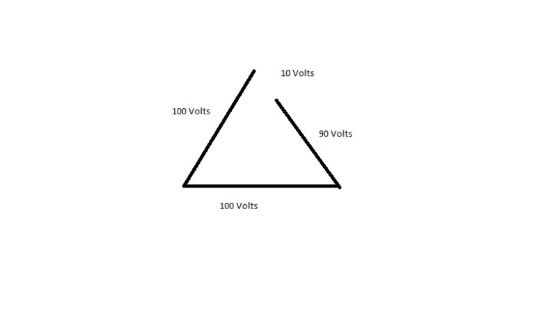
Single phase loads. The sketch of the delta does not reflect the action of the delta with unbalances.
delta_ddpvsn.jpg

A single phase load causes a voltage drop on that phase. As a result the voltages supplied to the delta are no longer equal.
For the sake of illustration assume that a single phase load causes a 10 Volt drop on a 100 Volt circuit.
That leg of the delta now has 90 Volts applied. The 10 Volt deficit causes a circulating current in the delta, limited by three times the PU impedance. The current in the neutral will be an effect of the 10 Volt deficit and will not be related to the phase or line currents.
Summary;
Harmonic currents coincide and add on the neutral.
Fundamental frequency unbalanced currents do not coincide on the neutral and add vectorilly. Only the vector difference flows in the neutral.
I should mention that I spent some years in an area where the grounded wye:delta connection was a common distribution connection.
The various effects of the connection became a fascination with me. My version of "Counting Sheep: was trying to visualize all the effects of the grounded wye:delta.
Ya, I know, I should get a life. grin.

Bill
--------------------
"Why not the best?"
Jimmy Carter
 
Bill,
"The current in the neutral will be an effect of the 10 Volt deficit and will not be related to the phase or line currents."

Big disagreement here, definitely related to the line currents per Kirchhoff.

"Fundamental frequency unbalanced currents do not coincide on the neutral and add vectorilly. Only the vector difference flows in the neutral."

Now we agree. This summation is 3I0, and the fact that I0 is by definition in phase everywhere makes the math easy. I made it a bit easier by ignoring the only non-zero sequence current present, the negligible amount of magnetizing current of the transformer. Remember the 480 V side is disconnected, so we're effectively filtering out all positive and negative sequence currents.

I think voltage confuses the issue, since impedance must be known to get to current. The impedance is not just the transformer impedance, but includes the effective impedance beyond the transformer transformed by the square of the turns ratio. The action of a transformer can be explained using current only.

Not our preference for new services, but lots wye-deltas are still in existence on legacy systems

As to the fix, perhaps the OP could either float the transformer neutral connection, or insert an impedance. It likely depends on the operating modes he has in mind.

prc,

More info please. Perhaps a sketch. Where is the load, how is it connected, where is the source, etc..

 
Hi StevenF
From the original post: 120 Amps per phase.- 360 Amps on the neutral.
Pure harmonics. No unbalance to cause circulating currents.
If there was 120 Amps, 120 Amps, and 140 Amps on a straight wye connection, we could expect 10 Amps on the neutral.
Where the circulating current problem arises is if the system is soft and the load causes a noticeable voltage drop on the heavier loaded phase.
That voltage drop will cause the circulating currents.
This is a harmonic problem.
The delta is acting as a short circuit to the harmonic voltages. Full load current on that transformer at 120 Volts is around 2000 Amps.
It won't take much harmonic voltage to drive 120 Amps through that delta in a short circuit condition.
The solution to the problem may be to open or break the delta.
As for legacy systems, I lived in a country where the grounded wye:delta system was the standard. The problems associated with it came standard as well.
When I was young I believed that electric theory was absolute and not subject to things like politics and local culture.
I found out different.
In the local culture it was common for the suppliers to give a large referral fee (kick back) to any engineer or electrician bringing in an order for transformers.
Generally the engineer would submit an order to a supplier and the bill would be sent to the owner.
As a result, transformers tended to be oversized. (More expensive = more graft).
I saw a 150 KVA transformer bank installed to supply a 17 KVA battery charger.
Many times the circulating current will cause a primary fuse to open. Then the oversized transformer bank works well and problem free as an open delta connection.
It was common when driving around town to see almost every three phase transformer bank with one fused cut-out hanging open.
Yes, grounded wye:delta systems with three phase switching and balanced loads work fairly well.
With single phase protection by individual fused cut-outs and frequent power outages and loss of phase events, You will see lots of problems.
The most frequent issues are burned out domestic refrigerators and burned out transformers.

Bill
--------------------
"Why not the best?"
Jimmy Carter
 
Status
Not open for further replies.

Part and Inventory Search

Sponsor