Continue to Site

Eng-Tips is the largest engineering community on the Internet

Intelligent Work Forums for Engineering Professionals

  • Congratulations KootK on being selected by the Eng-Tips community for having the most helpful posts in the forums last week. Way to Go!

Parasitic Resistance

Status
Not open for further replies.

jvjtech

Electrical
Dec 26, 2007
22
I may have a problem with parasitic resistance, not parasitic capacitance, in a customer's 600 Vac system. It appears that a parasitic resistance, in the order of a few 100 kOhms or single digit megohms, is appearing from the neutral to ground, effectively in parallel to the neutral grounding resistor (NGR).

In thread238-199182 Oldfieldguy says "I have found that in many cases there is sufficient capacitive and resistive path to ground, like a connected MCC's buswork, ... ". I would like to know what Oldfieldguy means by "sufficient".

I suspect that in my case, leakage in various MCC systems is cumulative and is appearing as a parasitic resistance from the neutral to ground.

I will add that while it is possible, I do not think that any bleeder resistors as discussed in thread238-45575 have been added to the connected equipment.

Any information as to what can be expected in the way of parasitic resistance is welcome.

Parasitic capacitance is not causing problems.

Thanks all.
 
Replies continue below

Recommended for you

A meg ohm in parallel with the neutral grounding resistance?
On a 600V MCC a Meg ohm from line to ground would result in about 1/3 ma leakage current. How did you detect a meg ohm in parallel with the grounding resistance? On a 600 volt system a 347 ohm neutral resistor will limit the ground fault to 1 amp. 1 meg ohm in parallel will result in a combined resistance of 347.88 ohms. This will result in a ground fault current of 1.000347 amps.
At 480 volts the difference will be less.
Have I misunderstood something here?
What is leading you to believe you have a problem?
respectfully
 
I have a relay that is designed to detect an open NGR. With no system power and the plant wiring / neutral connected to the relay, the relay does not work as expected, i.e. the relay does not indicate an NGR failure when the NGR circuit is opened. With the relay disconnected from the neutral and the plant wiring / neutral is disconnected from the relay, the relay does indicate an NGR failure when the NGR circuit is opened. This leads me to suspect that leakage in the plant wiring, specifically resistance, is preventing the relay from detecting the NGR failure.

My apologies, but I have to withhold some information that would shed more light on the situation. I hope this helps a bit.

Thanks again.
 
Waross: I just noted that you, as I do, work in Canada. As I am sure you know, the CSA mining code includes a requirement for the detection of an NGR failure. Hence, the reason for my original post.
Regards. JVJ
 
Is the relay an integral part of the neutral grounding device?
Can you give us enough information (eg. make and model #) of your grounding device and relay that we may google up a circuit drawing?
What is the ohmic value of your neutral grounding device? What ground current is allowed to flow during a ground fault?
Thanks
respectfully
 
Waross: Again, I apologize but all I can add at this time follows. The Let Through Current specified by the customer is 100 mA which makes for an NGR value of 3470 Ohms. The relay is connected to the NGR through a 138 kOhm sense resistor. The sense resistor connects to the same terminal on the NGR that connects to the system neutral at the X0 terminal of a 13.8kV/600V transformer.
Thanks again. JVJ
 
Hi jvjtech.

What are the inputs to your NGR monitor? You mentioned the neutral connection. Are there others? Voltage? Current? Or is it just monitoring the resistance of the NGR?

Where are you opening the NGR circuit?
 
I'm traveling to spend some time with my children. Be in transit for about 24 hours. I'll get back to you in a day or so.
Yours
Bill
 
The relay has two inputs, one from a CT monitoring the current through the NGR and one, a voltage input, from the sense resistor described earlier.

When system power is on and if the relay detects measurable current through the NGR it uses this value with the input from the sense resistor to determine the resistance of the NGR and then see if it is within tolerance.

When system power is off there is, or there no current through the NGR, the relay injects a signal through the sense resistor to determine if there is continuity through the NGR to ground.

When the connection from the NGR to the GND is removed, with the other connection left intact, the relay does not indicate an NGR failure as expected. However, if this connection is left intact and the connections to the X0 terminal and through it to the plant wiring and are removed the relay does indicate an NGR failure as expected.

This leads me to believe that the presence of plant wiring is appearing as as a high impedance/resistance to ground mirroring continuity through the NGR to ground. Admittedly, this would be a high, very high, resistance in the range of a few 100 kOhms or single digit megohms.

Thanks all and safe travels Bill. jvjtech
 
Thanks for the good wishes.
Where are you disconnecting the NGR from ground? My understanding is that the detection is to detect a failure of the NGR resistor not intentional disconnection. I may be wrong here. Is the ground lead of the resistor connected to the ground end of the NGR or to a separate ground connection?
You may have an inadvertent neutral ground connection bypassing the NGR.
Have you considered connecting a known resistor from one line to ground. Something in the range of 7000 ohms or higher.
From there, measure the voltage across your test resistor and the NGR. They should sum to 347 volts. If not,there may be some reactance in the NGR. From the voltages and the known resistance of the test resistor you should be able to calculate the current and the impedance from line to ground to neutral of the NGR plus any parallel resistance. I'm still quite tired. I may make more sense tomorrow.
respectflly
 
Waross: Your suggestion to add a fault using a known high resistance makes sense to me. If I fault the system with a 6940 Ohm resistance I will have a 1/3 to 2/3 relationship in the resistive elements of the resulting voltage divider. Any difference in this ratio would be due to the contribution of the suspected parasitic resistance. I am aware that the impedance of the parasitic capacitance has to be considered as well but this should be a constant.

Other tests at the site, with a low resistance intentional fault, showed a current of 800 mA at the point of the fault. Without an NGR the fault should have drawn significantly more than 800 mA but was limited by the NGR. As the current at the NGR would be 100 mA and if my math is correct, this shows the impedance of the parasitic capacitance to be 27517 Ohms, ignoring the contribution of the suspected parasitic resistance. The parasitic capacitance works to to be 0.010 uF.

I will do some more work on the vector math involving the combination of the suspected parasitic resistance, the NGR, the fault resistance and the calculated impedance of the parasitic capacitance above to see what to expect in the voltage divider presented by these elements. This work should also show what to expect if one element is varied as described above. And, from that, how to discern if there is indeed a parasitic resistance in the system.

The intentional removal of the NGR to ground connection is intended to simulate a failure of the NGR for the purposes of testing the relay's capability of detecting the failure. This connection is made through a wire at a terminal strip. I do not think that there is any other path to ground, e.g. chassis, mountings, etc. in the mix except for the parasitic impedances in the system, i.e. capacitance and resistance.

I have read guidelines on the net that state that in tests of the insulation of plant wiring, conducted with a megger, the plant wiring should present a resistance to ground in the order of 100s of megohms. These guidelines also state that these these tests should be conducted with the MCC equipment disconnected.

Thanks. JVJ.
 
I am going to ballpark this, assuming that everything is resistive.
347V / 800 ma = 434 Ohm.
1 / ([1 / 434] - [1 / 3470]) = 496 ohm
Reality check:
100 ma = 3470 ohm
700 ma = 3470/7 = 495.7 ohm.
You are looking for an impedance in the order of magnitude of 496 Ohms.
You may want to intentionally ground each phase in turn.
Approximately equal currents indicate leakage. One phase much higher than the others indicates a single point contact.
With a ratio of 7:1 between known and unknown impedances, the unknown impedance will predominate, even if it is reactive.
By far the easiest and quickest, possibly by days, is to reapply your intentional ground, and de-energize your system, step by step until the leakage current drops.
More later
respectfully
 
Waross et al. You have given me a lot of information to work with over the next while. I am not sure when I will be be able to update this thread with a definitive outcome. I want to say thanks for your help before this thread goes stale and is closed. Thanks and Regards.
 
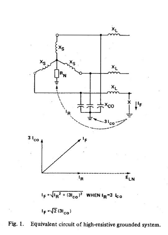
I thought I would post a graphic of the vectors associated with fault and capacitive charging currents in a high resistance grounded system using an NGR (RN). This graphic does not show the suspected parasitic resistance that was the reason for the original post. Regards.
ngr3icoequivcircuit5x7.jpg
 
Hi Slava, Thanks for the informative diagrams of a faulted system showing the capacitive charging and fault currents in the system. As your diagram shows no charging current in the faulted phase it follows that the vector diagram in the graphic I posted should be using 2Ico rather than 3Ico.

Please note that the graphic I posted shows a series impedance XL in the feeder which may serving to isolate IF from 3xIco. I will study this and try to reconcile the differences.

I noted that your diagram also shows the resistive leakage (R0) that prompted my original post. The accompanying text notes that resistive leakage losses are neglected for the purposes of the analysis. Regards.
 
Hello Jvjtech.
From time to time we try found some "big" problem and don't put attention on small things.
I would like recommend you check installation of monitor and all devices included, that they are installed according to all requerements of vendor.
Once I had such problems in other system, only change of
wiring of VT connection from 6mm^2 to 35mm^2 helped me.
Injection module ( that check resistance to grounding) was 3 meter from monitor instead 0.5meter.
Try check.
Good Luck.
Slava.
Could you please send us link to this device.
 
Hello Waross, Slava and others.

The source of the resistive leakage path to ground has been identified as a resistor network in a piece of equipment that, by design, includes a High R path to ground. This High R leakage resistance is in the order of a few hundred kOhms. As Slava suggested, we had to look for a more practical root of the problem and not some of the more elusive possible causes such as “parasitic resistance”.

Once again I hope you will forgive me for withholding some information as there are many players involved including various suppliers, manufacturers, integrators and, of course, the customer.

Thanks again all.

Waross: Congrats on being voted TipMaster of the Week.
Regards.

 
Hello Jvjtech.
Thanks for the feed back.
Good Luck.
Slava
 
Status
Not open for further replies.

Part and Inventory Search

Sponsor