Continue to Site

Eng-Tips is the largest engineering community on the Internet

Intelligent Work Forums for Engineering Professionals

  • Congratulations KootK on being selected by the Eng-Tips community for having the most helpful posts in the forums last week. Way to Go!

roll pin application

Status
Not open for further replies.

stevenal

Electrical
Aug 20, 2001
3,796
Full disclosure: The device in question is more hobby than work related. But as engineers, safety is paramount is all aspects of our lives. Since my question is safety related, and I'm thinking of making a report to the relevant government agency, I believe my question should be allowed.
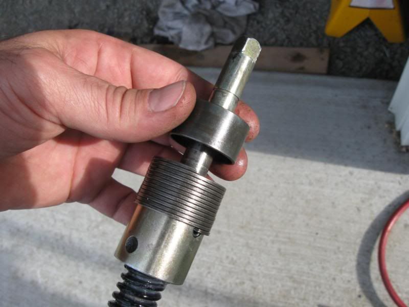
IMG_1004.jpg

Please see the connection between the threaded rod and collar in the photo. The threads don't end at the bottom of the collar, but extend to the top of the rod above the pin connection. The inside of the collar is cylindrical, not threaded. This means the pin crosses a bit of a gap, unlike the upper pin which joins a cylindrical shaft and hole. I believe the gap causes some of the stress on the pin to be bending moment instead of straight shear like in the upper pin. Is this EE correct on this mechanical issue? Is this a proper application? I had a pin like this one (not my photo) fail at a time when it caused no safety issue, but at another time it might have caused a motor vehicle accident. Thanks.
 
Replies continue below

Recommended for you

Nothing wrong with having suspected bending load as long as the design accommodates the condition.

Ted
 
It also seems likely that the pin is intended to break in case of overload.
 
I see more information is needed. The photo is of the internal parts of a truck camper jack, used to lift a camper on and off a PU truck. The jack is operated via a hand crank, with a motor drive as an option. The motor has a clutch that slips in case of mechanical overload, and a fuse for electrical overload. The pin holds the jack leg up when it is retracted and the camper is on the truck. The failure caused the jack leg to drop to the ground suddenly when the rig was parked. Dropping when on the highway will have a different result. If a failure occurred when extended and supporting the camper, there would still be friction present to slow or stop the descent of the camper.

In my review of spring roll pins specifications on-line, I have found shear strength information but no bending moment specs, leading me to believe this might be a misapplication.
 
Is the pin under load when the jack is extended and supporting the camper? That would be inappropriate. Can you tell if the pin failed due to vertical load or twisting load? Is the pin the only element transmitting torque from the collar to the screw? You will probably have to due the calculations to determine pin bending capacity.

Ted
 
"Is the pin under load when the jack is extended and supporting the camper?."
The weight would tend to push the assembly together against the stop, so no vertical load to speak of. The freewheeling ball screw would tend to transmit some torque, but even with the motor assembly removed there is enough friction in the right angle gear above to prevent the screw from backing down. Instructions advise only letting the camper sit on the jacks long enough to load/unload. Failure in this manner is not my main concern.

"Can you tell if the pin failed due to vertical load or twisting load?"
The crumbs left gouges to the side inside the collar, so I would say twisting load. I'm guessing that stopping/starting/reversing the motor took it's toll, since I was careful to avoid letting the clutch slip when fully retracting it.

"Is the pin the only element transmitting torque from the collar to the screw?" Yes.

"You will probably have to due the calculations to determine pin bending capacity." And compare to what? It's the lack of published specs on bending moment and the brittle nature of the pin that lead me to believe that it may be a misapplication to use where any significant bending moment is involved.

Jack is rated 1900 lbs and four of them are used on a 1900 lb dry weight camper.
 
Compare to what? The torque at which the clutch slips. That would be the input limit to the pin drive.

Ted
 
I suppose from the torque one could calculate the applied moment, but I would still need a roll pin specification to compare it to. I suppose I could initiate some testing, but I doubt even the manufacturer has done so.

Withoutut testing or calculating, can the group state anything regarding whether they believe this is a proper application? Thanks.
 
Hi Stevenal
I would say that putting a roll pin through a thread was a normal application, the pin is used sometimes to prevent rotation of a threaded joint loosening under vibration or if it is subjected to a load it should be sized and selected to take the required service load see this link


Now if over a period of time the pin as worn the hole that was first drilled to accept it, it's possible that the pin would see a slight impact load every time the device is used in which case it may fail due to fatigue.
 
Thanks desertfox. Your link like the others specifies shear only. While it might be normal to pin a threaded joint, this does not qualify since only the rod is threaded; leaving the gap I spoke of. The pin holes do not appear to have worn.
 
It's not strictly a correct application, since the pin manufacturers typically specify only shear, and don't publish the material specs that would allow you to evaluate an application where a bending moment exists, as here.

I.e., I wouldn't do it that way.
If forced to do so, I'd oversize the pin.

If I had merely purchased the jack, and it had failed once already, I might try filling the cup cavity with JB Weld or other filled/hard epoxy during assembly, in an attempt to place the pin in pure-ish shear.

If that didn't work, I might replace the rolpin with a solid hardened dowel, and retain it with an external sleeve or circlip around the cup.


Mike Halloran
Pembroke Pines, FL, USA
 
Atwood or Happijac jack? There are some rv threads referencing Happijac failure.

If you think about it, the pin would tolerate higher loading in bending than shear. Bending failure is result of exceeding yield or ultimate tensile strength which are both higher than shear strength. How much clearance is there that the pin must span? Less than a pin diameter?

I would guess some other failure mechanism is at work here. Perhaps impact.

Ted
 
Happijac. Might even see a Stevenal response if you are looking at the right forum. Yes, probably less than a pin diameter of gap on each side.
 
Hi stevenal

I've visited the Happijac website and saw the piece on there that matches your photograph to get a better understanding of the problem.
Rereading your original post and the information I found on the link in my last post I can see that the pin would have to transmit the torque from the motor or hand crank operation and I don't think that's a brilliant idea.
The gap would possibly cause some bending on the pin and not just pure shear and also the pin would be subject forward and reverse torque during lifting and lowering.
How old is your jack? as I can see the pin being subject to impact loading particularly if the holes in the adjoining components start to wear, in addition there is the possibility of fatigue failure also.
To get some idea of the torque the pin would have to transmit you could use the relationship:-

P (lifting capacity) = Torque/(0.02*d) where d = ball screw dia and 0.02 = friction factor

So transpose the formula to get torque, use the lift capacity of the jack and diameter of the ball screw to get the torque. Once you have the torque we can look at the size of pin and the related shear stress/ bending.

I think you might have a good point in your original post and I suppose its whether the manufacturer can demonstrate that the pin was designed fit for the purpose.
 
Thanks. The jacks are about three years old. I'd say the gap exceeds the .15 mm from the pdf. The gap would be approximately equal to the thread depth at its greatest. I've gone ahead and made my report to the NHTSA. To my surprise, I have received email confirmation asking for a few more details, so it looks like they might actually be looking into it. The other similar jack (rear jacks are an acme screw model) was making noise the other day, so I'll be disassembling it before next use.
 
Hi stevenal

Have you any pictures of the failed pin itself? if so looking at it might also give a clue to its failure.
In addition look at the hole the pin goes through and see if there is any elongation of the hole ie should look like a very small slot.

good luck

desertfox
 
I noticed no elongation. I took no pictures myself, the one above was borrowed. Here's another borrowed one that looks similar to what I saw:
Hjacpin.jpg
Mine had more pin fragments.
 
Hi Again

Is the piece of pin sat on the base from the centre of the bore or is it part of the piece through the hole on the right hand side of the main piece.
Also looking at the piece of pin the face looks as though its failed at a slight angle?
Any chance of a real close up on the fractured spirol pin face, trying to look for clues of failure but I can see it was a brittle failure looking at it.
A little trick to test for brittle failure is if you have both half's of the failed pin then try putting them together, if they fit together quite easy a bit like a jigsaw puzzle then its usually a brittle fracture, if its a ductile fracture there is usually a lot of distortion and the failed bits don't quite fit together.

desertfox
 
Again it's not a picture of my jack, but of a similar failure involving fewer fragments. I'll try to get pictures when I tear down the other one, but other projects are ahead in the queue. Definitely a brittle failure. I don't believe these hard pins will bend or distort much other than the tiny bit of spring action upon assembly. With bending moment they just break.
 
Status
Not open for further replies.

Part and Inventory Search

Sponsor