Continue to Site

Eng-Tips is the largest engineering community on the Internet

Intelligent Work Forums for Engineering Professionals

  • Congratulations KootK on being selected by the Eng-Tips community for having the most helpful posts in the forums last week. Way to Go!

Woodworks Shearwalls Verification

Status
Not open for further replies.

medeek

Structural
Mar 16, 2013
1,104
Recently I've been analyzing a number of mixed two story/one story residential designs using Woodwork's shearwall software. It has become my go to product for determining my shearwall forces for many of my jobs that are too complex to realistically do wind and seismic load takedowns manually. However, it always makes me a little uneasy using a product like this and putting all one eggs into one basket especially when I don't have a "second opinion" on the forces. After a number of jobs I do have a rough feel for what sorts of numbers I should expect which has actually saved me on one job that went wrong in the Woodworks shearwall software. Does anyone have any suggestions on software or methods that could be utilized to economically validate the output of the Woodwork's shearwall software.

On a similar note, I have lately been enveloping the design with flexible and rigid diaphragm analysis however I am finding my shearwall forces are sometimes ridiculously high. Since I think most of us can agree that the actual diaphragm behavior is somewhere in between these two extremes (semi-rigid diaphrahm) perhaps it would be more realistic to take the enveloped shear force (maximum of the two) and take some percentage of it, say 75% versus using the maximum force.

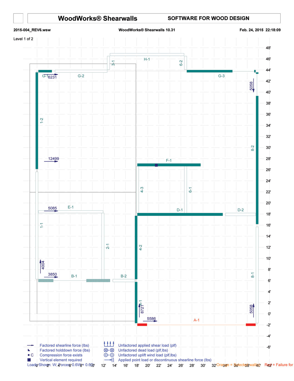
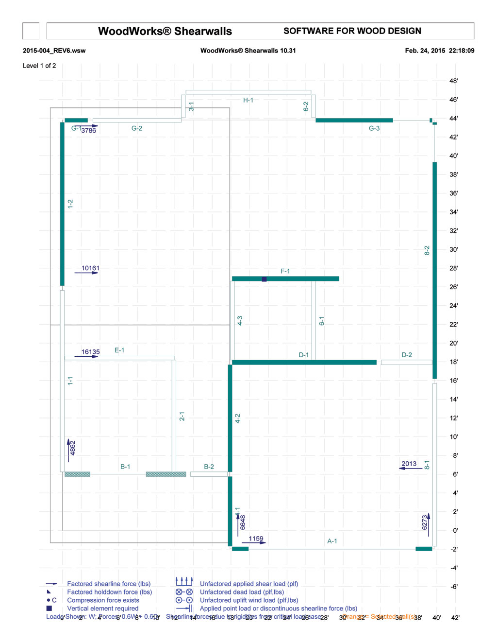
Case in point is the first level of the residence shown below. If I take the max. shear load to each shearwall from either the rigid or flexible analysis it would seem to me that I am over designing the structure to some extent.

A confused student is a good student.
Nathaniel P. Wilkerson, PE
 
Replies continue below

Recommended for you

Flexible Diaphragm Analysis:

2015-004_REV6_WIND_FLEXIBLE_LEVEL1.jpg


Rigid Diaphragm Analysis:

2015-004_REV6_WIND_RIGID_LEVEL1.jpg


A confused student is a good student.
Nathaniel P. Wilkerson, PE
 
There was a push a few years ago to take the worst case of a rigid diaphragm analysis and a flexible diaphragm analysis. It is extremely conservative in my opinion. If I go directly by the code, I can use just flexible which can help and hurt in some cases. Your 75% concept seems reasonable and safe. I might average them. I know woodworks gives you both results and lets you decide what to do.

We do know that the real condition is semi-rigid diaphragm. We also know that wood structures in general have a great deal of ductility. I wouldn't punish your design too much. There are a LOT of factors involved in how these structures really behave and there are plenty of real world examples of houses that shouldn't work, but are somehow still there.

When I am working on a problem, I never think about beauty but when I have finished, if the solution is not beautiful, I know it is wrong.

-R. Buckminster Fuller
 
In the last few designs I have had Woodworks at my disposal so both analyses were present (rigid and flexible), thus allowing me to envelope the designs however after some recent flack from local contractors I'm leaning towards a less conservative approach that takes me a little closer to the edge. If I go too conservative it obviously costs more too build and that is a major factor from the customers standpoint. I need to compromise somehow...

A confused student is a good student.
Nathaniel P. Wilkerson, PE
 
I personally think it is a waste of time to use woodworks for a residential structure. There is too much redundancy and other issues going on that make the output worth using. You will end up spending way too much time and making your designs way too conservative. I typically just calculate the overall wind load and use the eyeball method to distribute it as I see fit. As Manstrom said," There are a LOT of factors involved in how these structures really behave and there are plenty of real world examples of houses that shouldn't work, but are somehow still there."
 
As long as you're satisfying equilibrium, I'm quite happy with running both analyses and just tossing out the one that would yield the least economical design. I know, you don't often hear an engineer advocate a lower bound solution. The truth is that our ability to make accurate predictions in this realm is very limited. Besides, a rigorous load path and thoughtful detailing is more important than "knowing" the loads accurately.

I like to debate structural engineering theory -- a lot. If I challenge you on something, know that I'm doing so because I respect your opinion enough to either change it or adopt it.
 
The problem with lateral design of wood framed structures, is that it depends on the flexibility of the diaphragm and shearwalls. If you look at your shearwalls along A-1, say the piers will resist 6000# with 1" deflection. If the diaphragm will only allow a 1/2" deflection along line A-1. Then the piers can only resist 3000#. The other 3000# must be taken by other shearwalls. So the design becomes a game of where and how much deflection occurs.

Garth Dreger PE - AZ Phoenix area
As EOR's we should take the responsibility to design our structures to support the components we allow in our design per that industry standards.
 
Typically one result is significantly lower than the other so 75% of the max. would be more conservative. However, a possibly better algorithm might be:

The maximum of either:

1.) 75% of the max. of Rigid or Flexible

2.) Average of the Rigid and Flexible


In pseudo code: MAX[ .75*MAX(R,F) , AVG(R,F) ]


A confused student is a good student.
Nathaniel P. Wilkerson, PE
 
Previously (prior to using Woodworks) I generally did a flexible analysis manually and that seemed to work fine for most simple structures (ie. rectangular garages), but then as I attacked more cut up roof lines and designs with too many windows on some walls the necessity for considering a rigid analysis drove me towards Woodworks and a more complex analysis. Now I am finding with the enveloped design method prescribed by certain texts I am perhaps a bit too conservative and it is hurting customer satisfaction and even confidence.

A confused student is a good student.
Nathaniel P. Wilkerson, PE
 
I agree Woodman88, my algorithm kind of breaks down when you consider the situation at A1 (in this case an eventual double portal frame at a garage opening). Realistically the portal frame is not going to resist 6000 lbs, hence the need for the rigid analysis in the first place. With the rigid analysis D-1 loads up quite heavily, if I am assuming that the garage opening really can't resist much load then taking a reduction or average of the loads to D-1 might not be fair in this case.

A confused student is a good student.
Nathaniel P. Wilkerson, PE
 
I can see XR250's point in the eyeball method. It might be to difficult to concoct a formula that is a one size fits all. With shearwall lines A, B and G it is fairly clear that the rigid analysis is more reasonable.

A confused student is a good student.
Nathaniel P. Wilkerson, PE
 
Except for these three shearwalls (A,B, and G) a simple average also seems reasonable and a good compromise.

A confused student is a good student.
Nathaniel P. Wilkerson, PE
 
Status
Not open for further replies.

Part and Inventory Search

Sponsor