Continue to Site

Eng-Tips is the largest engineering community on the Internet

Intelligent Work Forums for Engineering Professionals

  • Congratulations Danlap on being selected by the Eng-Tips community for having the most helpful posts in the forums last week. Way to Go!

Pile to Cap Force Transfer 1

Status
Not open for further replies.

bookowski

Structural
Aug 29, 2010
981
This is related to but different than a recent post here.

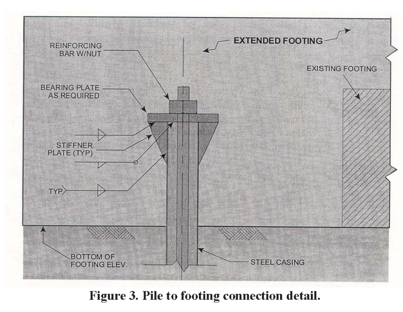
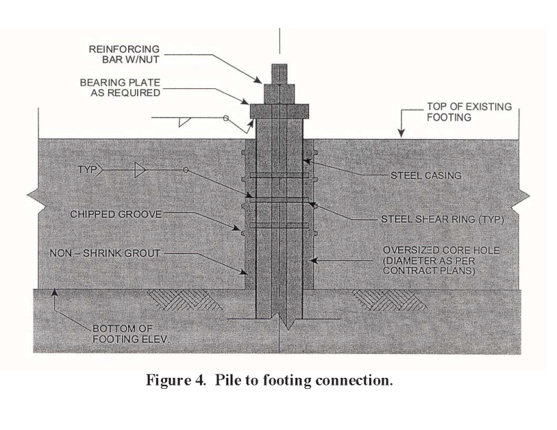
Pile type: steel pipe casing, center large diameter bar steel core, grout filled (to rock). For example 13-3/8 x 0.5" wall pipe with one #24 center bar, capacity ~400 tons (800 kips).

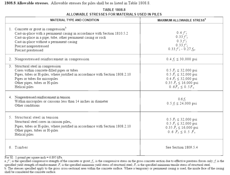
The design of the pile capacity comes from code allowable stresses. The casing is designed using 0.5Fy (max 32ksi). What is the force transfer mechanism between the casing and the pile cap? The grout makes sense in straight bearing, center core bar can be developed or provided with additional anchor plates, but the casing? There is no way that the contact bearing based on 0.5Fy works for concrete and the embedment isn't sufficient for any kind of friction. Have used these many times but never thought about it. Am I missing something?
 
Replies continue below

Recommended for you

Just like that other thread, I think that your load path goes: pile cap --> concrete/rebar plug --> some proportion to casing --> ground.

I like to debate structural engineering theory -- a lot. If I challenge you on something, know that I'm doing so because I respect your opinion enough to either change it or adopt it.
 
This is in compression, and assuming that I'm fully utilizing the pile then you'd have to allow for a significant local overstress at the pile tip grout & core. In the example/dimensions that I gave above the casing should be able to take > 400kips compression. Assuming that the grout + core are already fully utilized you'd have to take this as overstress in the grout & core. I guess alternately you could add additional rebar at the top for a non-contact lap with the casing, but I never see this done.
 
Bearing stress on the pile area would probably be controlling. Having never used a 400 ton pile, I don't really know. Must be good rock at the bottom, the concrete has to be just as good.
 
Bookowski said:
This is in compression,

Yup. It's still the same load path though if you plan to take some of the compression in the casing.

Bookowski said:
I guess alternately you could add additional rebar at the top for a non-contact lap with the casing, but I never see this done.

Couldn't your centre #24 bar do this job? Perhaps I'm not understanding the detail.

I like to debate structural engineering theory -- a lot. If I challenge you on something, know that I'm doing so because I respect your opinion enough to either change it or adopt it.
 
Maybe this design is unique to the area/atypical. Attached is a sketch of the typical caisson in this area. It's a steel casing and center core large diameter bar that is continuous all the way to the base of pile. The center bar is fully counted for the capacity, it's not a lap/transfer bar. The capacity of the pile is given by: 033 x f'c x Agrout + 0.5 x Fy x A_Center Bar + 0.5 x Fy x A_casing.

The way I have always seen this implies that the center bar gets developed but I have never seen anything account for how the .5Fy x A_casing gets transferred. That force can be large and doesn't make sense (on paper anyway) in bearing just at the surface of the casing tip.
 
 http://files.engineering.com/getfile.aspx?folder=a31eb6ce-db81-4f3a-a66d-b66336949737&file=Typ_Caisson_-_Copy.png
bookowski said:
The center bar is fully counted for the capacity

bookowski said:
033 x f'c x Agrout + 0.5 x Fy x A_Center Bar + 0.5 x Fy x A_casing.

These two statements seem incongruous. Could it not be that some portion of the load approaching 0.5FyA of the center bar might be getting transferred from the center bar over to the casing?

It would be useful to see what the top and bottom details look like.

I like to debate structural engineering theory -- a lot. If I challenge you on something, know that I'm doing so because I respect your opinion enough to either change it or adopt it.
 
Why are they incongruous? The 0.5Fy is a working level stress that was decided eons ago. The factors of safety are low enough that in practice what you are saying could probably work, there's a lot of meat left in all the components.

The base detail is a socket to rock, varying in length depending on how much capacity you need. At the top it's usually a 6" embed of the casing into your cap the core bar either extends up to develop or gets a compression anchor plate.
 
Bookowski said:
Why are they incongruous? The 0.5Fy is a working level stress that was decided eons ago.

I guess they're not. As you surmised, I was thinking partial utilization of the steel in ULS.

No cap plate at the bottom of the pile, right?

As you and Hokie have both touched on, it sounds as though the casing needs to be non-participating at both the top and bottom of the pile with respect to bearing, unless there are cap plates involved. So if the casing is to participate meaningfully at all, there must be shear transfer between the casing and the idealized "plugs" at each end. Well confined concrete should be much stronger than the equation would indicate. Maybe some of the margin that makes it work resides there.

So I guess my final answer here is that I don't know a darn thing beyond what you started with.

I like to debate structural engineering theory -- a lot. If I challenge you on something, know that I'm doing so because I respect your opinion enough to either change it or adopt it.
 
Correct, no cap plate at the bottom. The steel casing gets socketed into the rock by some length determined by the geotech, beyond that length there is a rock socket which is grout and core bare only (the casing has dropped off) the length of which is also determined by demand. Capacity is combo of end bearing and friction. Base detail attached.

I guess maybe there isn't a logic but just enough cushion in the allowable stresses that it works. I thought maybe there was a trick that i was missing.
 
 http://files.engineering.com/getfile.aspx?folder=4efa798c-b044-442e-a987-2c88f8b019f4&file=Typ_Caisson_Base_Detail_-_Copy.png
bookowski said:
I guess maybe there isn't a logic but just enough cushion in the allowable stresses that it works. I thought maybe there was a trick that i was missing.

I think that you may have identified a bonafide mystery here. And if we can't identify the logic, that makes me a little queasy about applying the capacity equation. The tip detail that you uploaded suggests strongly, to me at least, that the force in the pile both leaves and enters the pile through the grout/rebar plug alone, just as you suggested initially. I don't understand why the casing should even enter into the capacity equation.

I like to debate structural engineering theory -- a lot. If I challenge you on something, know that I'm doing so because I respect your opinion enough to either change it or adopt it.
 
This has similarities to micropiles (albeit that your pile diamter is not so 'micro' at 13-3/8" diameter).

Some details that I have seen of the micro pile top-to-footing connection are as follows:

202_Practical_Advice_for_Fdn_Design_-_micropiles_figure_3_icnam6.png


202_Practical_Advice_for_Fdn_Design_-_micropiles_figure_4_ablysc.png
 
Agreed. This system is poplar in my domain: Link. When casing is used it is usually just there to a) prevent the grout hole from collapsing and b) provide some nominal lateral capacity.

I like to debate structural engineering theory -- a lot. If I challenge you on something, know that I'm doing so because I respect your opinion enough to either change it or adopt it.
 
bookowski,

This download Link by Dr. Donald BRUCE, et al, on micropile design maybe useful.
 
@Ingenuity: star for you; mystery solved.

@Bookowski: it appears that, in the absence of some kind of casing cap assembly, the plug capacity based on equation five of Ingenuity's attachment would require attention. I'm curious to see where you land with this.

I like to debate structural engineering theory -- a lot. If I challenge you on something, know that I'm doing so because I respect your opinion enough to either change it or adopt it.
 
I don't think that equation would be satisfied just based on eyeballing. My full capacity is 0.33f'c so I'm only gaining 7% there, I have 0.5Fy for the bar so I'm losing 3% there, and I'm losing the full casing strength. My capacity is given by the '08 NYC building code which is free online, the '14 code has similar equations as well with slightly different factors. From '08: 1810.7.5 Allowable stresses.The allowable design compressive stresses shall not exceed the following: concrete, 0.33f'c; steelpipe, 0.35Fyand structural steel core, 0.50Fy.

Seems like it just doesn't make sense in terms of load path but isn't causing any problems. I will update this if I figure out that it does make sense and I'm missing something.
 
I checked out the NY code clauses. They say that the allowable stresses should be as indicated below for the individual components. However, they do not directly specify the assembly combinations to be used for design. Presumably...

0.40 x f'c x A_grout + 0.5 x Fy x A_Center_Bar

...would be as applicable to the uncased length as...

0.33 x f'c x A_grout + 0.5 x Fy x A_Center_Bar + 0.5 x Fy x A_casing.

...would be to the cased length.

Capture_b5ez9w.png


I like to debate structural engineering theory -- a lot. If I challenge you on something, know that I'm doing so because I respect your opinion enough to either change it or adopt it.
 
No less confused... I will press the geotech a bit more. I have signed and sealed calcs but they don't shed much light on the underlying logic or lack thereof.

If your assumptions are correct then at the uncased length you gain 7% on the grout strength but drop off the entire casing. That 7% would not come close to what you've lost so the casing would be essentially useless. On the pile I'm looking at the casing is 15.5 square inches of 50ksi steel, that's a lot of force.
 
Yeah, given how much steel resides in the casing, it's hard to imagine why one would even bother with the threadbar unless it's to provide Some uplift capacity. Just make the casing a little thicker and save some operations.

I worry that responsibility for the connection between piles and supported structure tends to fall into a sort of no man's land (it should be EOR responsibility IMO). I use micro piles and screw piles all the time. The geotechnical engineer or piling contractor usually provides some conceptual detailing recommendations which may or may not suit the supported structure.

Designers then often take these details as gospel and consider their work done once the recommendations have been incorporated. I can't tell you how many pile cap and grade beam details I've seen on IFC structural drawings where piles would punch right through the supported structure if loaded anywhere near capacity.

I like to debate structural engineering theory -- a lot. If I challenge you on something, know that I'm doing so because I respect your opinion enough to either change it or adopt it.
 
Status
Not open for further replies.

Part and Inventory Search

Sponsor