Continue to Site

Eng-Tips is the largest engineering community on the Internet

Intelligent Work Forums for Engineering Professionals

  • Congratulations GregLocock on being selected by the Eng-Tips community for having the most helpful posts in the forums last week. Way to Go!

Structural Engineering Riddle of the Day 1

Status
Not open for further replies.

gharli

Structural
May 28, 2015
42
Dear All,

Perhaps this question warrants a major refresh of classic structural engineering mechanics (speaking for myself).

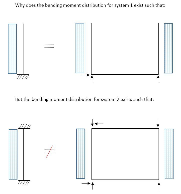
Why does the stiffness of the horizontal beam in system 1 have absolutely no bearing on the moment distribution in the vertical elements? i.e. the vertical elements in the frame of system 1 are exactly the same as modelling an infinitely stiff joint (encastre). Changing the stiffness of the beam has no effect on moments.

Whereas, the stiffeness of the horizontal beams in system 2 have a marked effect on the moment distribution in the vertical elements, i.e. modelling infinitely stiff ends obviously results in higher vertical end moments.

See picture below, the wording isn't 100% accurate it should read "vertical bending moment distribution"
RiddleOfTheDay_yz0zuw.jpg
 
Replies continue below

Recommended for you

SDOF

"Programming today is a race between software engineers striving to build bigger and better idiot-proof programs, and the Universe trying to produce bigger and better idiots. So far, the Universe is winning."
 
Nice and succinct but still confusing. Are you stating the system 1 has a single degree of freedom and system 2 has 2 DOFs?

_________________
Jones & Wagener
 
System one is statically determinate. The vertical element internal forces can be solved directly.
System two is statically indeterminate. The vertical element internal forces are dependent on the stiffness and forces in the other members.

 
Well, I guess I have to go back to school because I have no idea what your diagram is trying to convey.
 
Na it has nothing to do with school. You want all the part marks you can get there - so you draw your diagrams as well as possible. I don't understand what you're trying to show at all. Labels, axes, more text to explain what you want to convey...all would be helpful for someone else to understand what you're trying to show.
 
I agree with SteelPE and allgodonames. Neither the question nor the diagram make a lick of sense to me.
 
The left side assumes infinitely rigid, the right side is not infinitely rigid, it is only as rigid as the members framing into the joint. Thus the joint moments will be smaller on the right hand side, how much smaller depends on the stiffness of the vertical and horizontal elements.

Now as to what the riddle is, I have not idea.
 
another vote for lousy sketches.

are the blue boxes UDLs ?

why would a UDL on a standing cantilever have anything to do with the RHS sketch, whatever that means ??

ok, the LHS of the 2nd sketch is a double cantilever, and so redundant; big deal, easy to solve.
RHS of 2nd sketch means what ?

another day in paradise, or is paradise one day closer ?
 
Ok, the votes have been tallied and it is indeed lousy sketch.

Some would say that democracy is three wolves and sheep voting on what to eat for lunch... Ok, but admittedly in this case it sincerely wasn't the best way to convey the question.

Ignoring the sketch, the question really was why is the BM distribution in a certain frame independent of the stiffness of the connecting members?

Bootlegend seemed to understand the somewhat (ok, very) backwards way of asking the question so Kudos to him.

The answer is that in a statically determinant system the bending moment distribution is independent of the relative stiffness of the connecting members.


_________________
Jones & Wagener
 
Tough crowd.

The sketches seemed clear enough to me, and whilst the answer to the question should be pretty obvious to any experienced structural engineer, it doesn't hurt to take a fresh look at things we take for granted, and for a student/inexperienced engineer I think this sort of question helps to generate understanding of structural behaviour.

Doug Jenkins
Interactive Design Services
 
Just to continue along the IDS philosophy, the System 1 columns on the right have nearly the same moment as the column with fixed base on the left but unless the beam is infinitely rigid, the ends of the beam rotate, causing the columns to rotate. The two columns on the right deflect y.tanθ more than the column on the left where θ is the beam rotation and y is the distance above the base. The moment is not exactly the same because the load decreases by a factor of cosθ which means the moment decreases by a factor of cos2θ.

In System 2, the columns on the right would have the same moment diagram as the single column on the left if both beams were infinitely rigid and the upper beam was prevented from translating horizontally or, to put it a little differently, if the columns on the right had the same boundary conditions as the one on the left.

BA
 
Yeah, first one is a statically determinate element.

Loads in the first cantilever can only go in one direction. Easy to distribute. Loads have a choice in the second figure, so stiffness comes into play.

Rotations and deflections are another matter -- stiffnesses (is that a word?) of all the elements are important in figuring out where these elements move to under loads.

"We shape our buildings, thereafter they shape us." -WSC
 
Sketches seemed pretty clear to me, gharli you should perhaps start another thread about the same problem with no sketches. That way it will better fit the standard architype of questions asked here, whereby we get to post 65 before anyone understands whats even being asked.... ;)

Had to laugh at BAretired's take on it, as correct as it is.

 
Status
Not open for further replies.

Part and Inventory Search

Sponsor