DarrenDM
Structural
- Mar 1, 2016
- 5
I am having some trouble with creating an appropriate ABAQUS model for the analysis of a large 3D arc box truss of the AT&T Stadium.
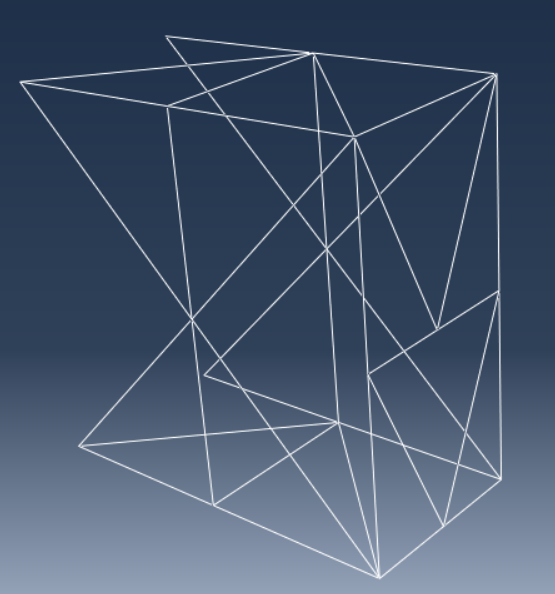
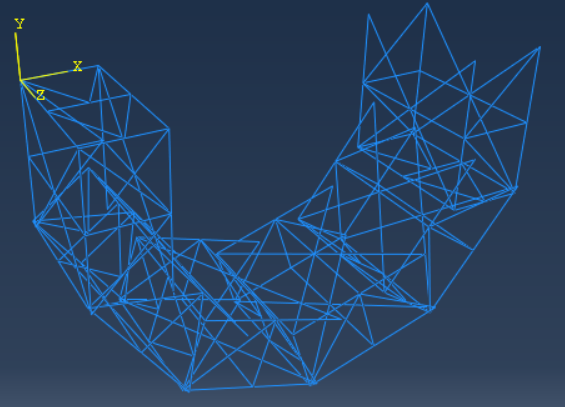
I have created a single PART for a box truss unit and I am trying to use the “radial pattern” tool in ASSEMBLY to repeat this unit roughly 46 times across a circular radii of 312 metre. When using the “radial pattern” tool, I cannot find the way to change the “centre of rotation” point and do the radial pattern produced is defaulted to a small circle. Also, I cannot seem to make the instance rotate on the appropriate axis as seen in the real life photograph of the truss as seen attached.
Additionally, once I figure out how to customise the radial pattern appropriately I must consider each nodes and ensure there are no overlapping or disconnected bars. I believe there is a “merge” option that will ensure this is not an issue. Furthermore, I need a way to overcome the small gap between each truss unit as it is square units copied around the diameter of a circle – is there a connection or additional member I must place between each to ensure the truss is correctly modelled without this small gap between each?


