Navigation
Install the app
How to install the app on iOS
Follow along with the video below to see how to install our site as a web app on your home screen.
Note: This feature may not be available in some browsers.
More options
Style variation
-
Congratulations MintJulep on being selected by the Eng-Tips community for having the most helpful posts in the forums last week. Way to Go!
You are using an out of date browser. It may not display this or other websites correctly.
You should upgrade or use an alternative browser.
You should upgrade or use an alternative browser.
Confused about DC motor neutral plane from theory to real world observations. 1
- Thread starter DenRR
- Start date
- Status
- Not open for further replies.
- Moderator
- #2
That is because the windings are skewed. The commutator segments are often not in line with the rotor poles. The windings are often run at an angle to allow for heat expansion. Then another factor is the distortion of the stator magnetic field by reaction with the rotor magnetic field. This may be compensated for by small poles called commutating poles or inter-poles.
Bill
--------------------
"Why not the best?"
Jimmy Carter
Bill
--------------------
"Why not the best?"
Jimmy Carter
Because the coil is in neutral position when it is under interpole area and due to the coil pitch, which is a pole apart normally, the commutator connection of the coil is physically located near the main field.
Muthu
Muthu
- Thread starter
- #4
SO basically what you guys are saying is that the coils of wire are under the neutral plane but the comm bars are energized by the brushes in the location over the magnets/poles. Hence, the reason for the brushes being located over the field/magnets instead of in the neutral plane as books like to show it. And they do this to allow better cooling and thermal expansion of the coils. Am I correct in comprehending what was said?
- Moderator
- #5
- Thread starter
- #6
I know its not static. Sometimes they may advance the brushes a few degrees I've seen to help the armature reaction at a specific load point. I don't work around the big daddy DC motors that have interpoles and compensating windings. Only the small boys that are no more than 25 horsepower. Usually Sep-ex and series wound for the wound field types and PM's up to about 3 horsepower.
DenRR
It is due to geometry. Imagine two coils, one pole part, undergoing commutation under interpoles. Where do they meet up? Under main pole.
The very idea of using interpoles is to have a stable & steady neutral axis from no-load to full load. The case where you have seen the brushes being advanced to achieve good commutation for a specific load is the classic case of a non-interpole machine. Now imagine doing all that moving brush back and forth for varying loads. That's why interpoles are used. To avoid such a moving back & forth.
Muthu
- Thread starter
- #8
We are not talking about interpoles here. Only about brushes being over the field poles OF EVERY DC MOTOR and not between them like motor theory books state. It's clear that the throw angle of the wires coming off the comm bars that is under the brushes puts the windings in the neutral plane instead of the brushes being in the neutral plane like they have done for old DC motor designs way back before my time. Books need to update to the latest design that DC motors use. It's annoying that they will not update them.
I very much doubt any good text book states what you claim.
Anyways, tried to help. You can take it or leave it.
Muthu
Anyways, tried to help. You can take it or leave it.
Muthu
-
1
- Moderator
- #10
The books are to demonstrate the theory in as simple and clear a way as possible.
Just to be sure we understand the neutral point:
Consider a simple armature. The conductor goes from a commutator segment to the core. It is wound around a rotor segment several times and returns to the next commutator. When that pole is midway between the field poles and is travelling parallel to the lines of flux, so that no voltage is developed in the coil, it is at the neutral point.
What is important is the position of the rotor pole.
Trying to draw the commutator offset in a simple drawing may add unnecessary complication.
Bill
--------------------
"Why not the best?"
Jimmy Carter
- Thread starter
- #11
In response to Edison123.
Have a look then at all the brushes being in the wrong locations compared to real world DC motors:
Wrong locations:
How brushes are actually located:
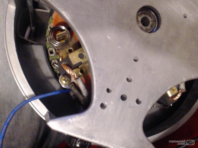
One of my personal electric motors:

"The books are to demonstrate the theory in as simple and clear a way as possible.
Just to be sure we understand the neutral point:
Consider a simple armature. The conductor goes from a commutator segment to the core. It is wound around a rotor segment several times and returns to the next commutator. When that pole is midway between the field poles and is travelling parallel to the lines of flux, so that no voltage is developed in the coil, it is at the neutral point.
What is important is the position of the rotor pole.
Trying to draw the commutator offset in a simple drawing may add unnecessary complication."
THANK YOU SIR!!! That is exactly what I needed. I gave you a star.
Have a look then at all the brushes being in the wrong locations compared to real world DC motors:
Wrong locations:
How brushes are actually located:
One of my personal electric motors:

"The books are to demonstrate the theory in as simple and clear a way as possible.
Just to be sure we understand the neutral point:
Consider a simple armature. The conductor goes from a commutator segment to the core. It is wound around a rotor segment several times and returns to the next commutator. When that pole is midway between the field poles and is travelling parallel to the lines of flux, so that no voltage is developed in the coil, it is at the neutral point.
What is important is the position of the rotor pole.
Trying to draw the commutator offset in a simple drawing may add unnecessary complication."
THANK YOU SIR!!! That is exactly what I needed. I gave you a star.
- Moderator
- #12
DenRR:
This link is a good example. You can see how cluttered and, dare I suggest, confusing, the drawing would become if the commutator segments were shown in their actual positions.
[link]Link[/url]
This drawing illustrates the brush shorting two commutator segments as it passes from one to the other. The coil that is shorted is not cutting any lines of force and the voltage is zero.
Note that in the interest of simplicity, the offset due to armature reaction is not shown in this drawing.
Bill
--------------------
"Why not the best?"
Jimmy Carter
- Thread starter
- #13
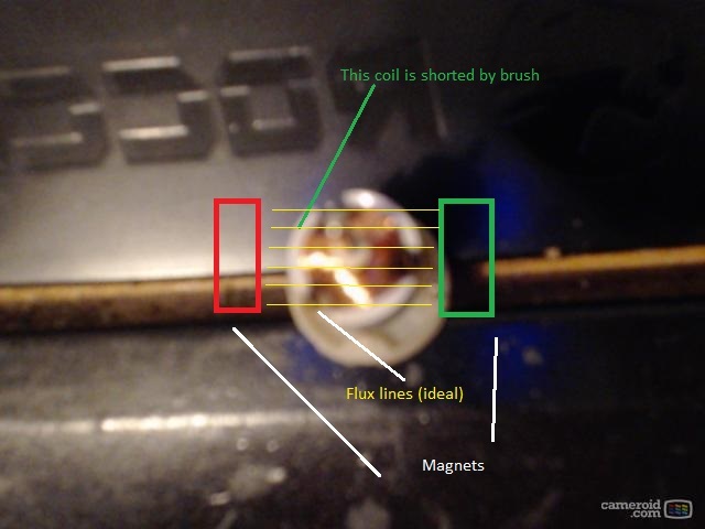
Now how about the special case when 3-pole armatures are used? I've found that a coil is shorted when the pole is directly in line with a magnet stator pole instead of between the poles.
Every three pole armature I found shorts two comm bars with one armature pole is facing directly perpendicular to a magnet. Is this a special case where they cannot avoid shorting a the coil when its at maximum generated voltage? Or do I need to look at the fact that the coil of wires will be parallel to the flux lines produced by the stator magnets? Or perhaps the flux lines are distorted and they accounted for it?
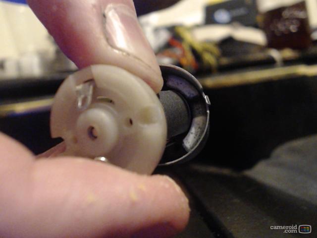
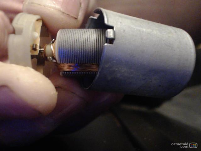
Here is a picture of what I am talking about:

- Moderator
- #14
- Thread starter
- #15
electricpete
Electrical
I came late to the thread. I haven't studied your photos and never heard of a 3-pole anything. I just wanted to respond to your original post (even though you've got it ironed out… I found a pretty good figure showing correct configuration and composed my response, so might as well post it for posterity).
I agree with you the depictions are not always correct in this respect. It's not too surprising that depictions in textbooks are different from the physical reality. Often a 3-phase stator is depicted as 3 "coils"…. it does not come close to the physical layout. I've had more than one new EE graduate express surprise/bafflement when I tried to describe the layout of coils set into slots and wired in pole-phase groups. Bill mentioned, sometimes there is need to omit certain details to keep things manageable. And we cannot assume that everyone who writes about motor theory on the internet has studied their physical construction.
Attached is a figure from EASA dc motors document which correctly captures the position of the brushes and matches edison's description very well. It is a 4-pole motor with stator poles are located at 12:00/3:00/6:00/9:00 on the figure. They tried to depict a diamond shape rotor coil and had to pivot it out so we could see the shape of the diamond in the figure… but in reality of course the coil sides (coil legs) are positioned axially and would only appears as a point on this figure … I have drawn in circles to show where the coil sides would be.
In the top figure the coil center is at 10:30 and the associated coil sides are located half a pole pitch away at 9:00 and 12:00. Rate of change of flux thru is maximum and current is flowing. The two leads of the coil are connected to two adjacent commutator segments which are generally (*) near the center of the coil (10:30 in this case).
The bottom figure represents coil moved to neutral plane with coil center (and associated commutator segments) at 12:00 and the coil sides are located half a pole pitch away at 10:30 and 1:30. Rate of change of flux thru coil is minimum/zero at this location and this is approximately where commutation should occur…which is why stationary brushes would have to be positioned at approx 12:00 (and 3/6/9) so this coil will be shorted when the brush overlaps the two associated segments and then reverse when the brush ends up on the other side of these segments.
Of course as you pointed out, we don't guess about neutral position.
* There are a large variety of winding configurations possible so I'm a little cautious about generalizations.
=====================================
(2B)+(2B)' ?
- Status
- Not open for further replies.
Similar threads
- Question
- Replies
- 6
- Views
- 9K
- Locked
- Question
- Replies
- 4
- Views
- 4K
- Locked
- Question
- Replies
- 6
- Views
- 4K
- Replies
- 9
- Views
- 11K
- Locked
- Question
- Replies
- 22
- Views
- 2K


