Continue to Site

Eng-Tips is the largest engineering community on the Internet

Intelligent Work Forums for Engineering Professionals

  • Congratulations GregLocock on being selected by the Eng-Tips community for having the most helpful posts in the forums last week. Way to Go!

Regeneration space theory in 4-quadrant regions of operation of DC motor 1

Status
Not open for further replies.

mawad

Mechanical
Dec 8, 2010
45
Dear All,
My background is mechanical and I was looking to understand the theory of regenerative braking in DC motors. I found this article online In Figure 3, it shows that in braking quadrants 2 and 4 there is regeneration space which you can regenerate energy within this space only and you need to apply voltage outside this space in quadrant 2 and 3 to brake or slow down the load.

I am wondering if there is textbook explain these issues and their theories. I only find this article and I looked for many textbook, but I couldn't find detail explaination of this point. Can you recommend me a textbook. I need urgently.

Thanks in adavance
 
Replies continue below

Recommended for you

I didn't like what I saw in that link. Not very clear and only about regeneration back to a DC source (or resistor, which I wouldn't call regeneration).

My favourite book is this: It covers all aspects of electric drive systems.

There are more texts available in German. Look for "Bremsen Rückspeisung Stromrichterantrieb" and such words. If you read German.

DC drives aren't very common today. But, as it happens, I am working on one right now. Mating an Arduino compatible controller with old thyristors and an old 440 V 760 A DC motor. Quite interesting and rewarding. I guess that I can answer any specific question that you may have.

Gunnar Englund
--------------------------------------
Half full - Half empty? I don't mind. It's what in it that counts.
 
Fundamentally, if the applied voltage is of the same sign as the back EMF voltage and of greater magnitude, you are motoring, converting electrical power to mechanical power.

If the applied voltage is of the same sign as the back EMF voltage and of lesser magnitude, or of the opposite sign, you are generating, converting mechanical power to electrical power.

When you are generating, the electrical power first goes to "charge up" the capacitors (or possibly batteries) on the DC bus, increasing the energy stored in them and increasing the bus voltage. From there several things can happen.

The next time you start motoring again, the stored energy can be used to create mechanical power, discharging the caps and lowering the bus voltage.

If the DC bus voltage gets over a certain threshold, a "shunt" resistor can be activated to dissipate the energy thermally.

If the front-end supply of the drive is sophisticated enough, the energy can be returned to the AC lines with the supply acting as an inverter.

If the bus voltage gets high enough without the ability to shunt current or return it to the lines, the energy can be converted to the kinetic energy of exploding components. (I've seen it happen...)

Curt Wilson
Omron Delta Tau

 
Following the KISS principle, Many DC machines are suitable for use as either motors or generators.
Before we get to the DC machines, consider the transfer of energy between batteries of slightly different voltages that are connected in parallel.
The current will flow from the battery with the higher voltage to the battery with the lower voltage.
For there to be a current flow, there must be a voltage difference.
The action of a DC machine with changing voltage, changing speed and changing field strength.
There are many different ways that an installation may regenerate so we will set up a hypothetical test bench that is able to mimic all conditions.
First we have an infinite, 110 Volt DC bus that may either deliver energy or absorb energy.
We are using a DC machine rated at 950 RPM and 100 Volts.
We also have a drive motor, the speed of which may be controlled.
We couple our DC machine under test to our drive motor.
We connect our DC machine under test to the infinite bus and it runs at a little below 1000 RPM.
Now we run the motor up to 1000 RPM and the back EMF equals 100 Volts (We stipulate this to be the case to Keep It Simple, Sam ).
The supply voltage equals the back EMF and there is no current flow, there is no motor action and there is no regeneration.
Now we drop the speed of the coupled drive motor slightly. As the speed drops, the back EMF drops and the test machine tries to drive the drive motor. When the speed has dropped to 950 RPM full torque is being developed as a motor.
Now we start our second test. We apply 100 Volts and turn the DC machine at 1000 RPM. Now we start to increase the speed. As we increase the speed, the back EMF increases above the applied voltage and energy is passed from the machine (Acting now as a generator) to the supply bus. When the machine reaches 1050 RPM it will be developing about full current as a generator.
The point is that there is only a few RPM difference between motoring and generating.
I have been onboard very large electric dragline machines watching the Wattmeter. The meter showed about 3 Mega-Watts being regenerated and fed back into the grid while the empty bucket was being dropped. (Eight x 1300 HP motor being overhauled will do that).

To reiterate our first lesson: There is a speed at which the back EMF equals the applied voltage and the machine is neither motoring nor generating. A little faster and it starts to generate. A little slower and it starts to motor.

Lesson #2, voltage.
Now we set up the machine to run at a constant 1000RPM. We state that our infinite bus now has a variable voltage.
With the speed kept constant at 1000 RPM and the field kept constant, we start to drop the voltage. As the supply voltage drops,
the back EMF is greater than the supply voltage. Energy is transferred from the DC machine to the bus. The machine is working as a generator. At a voltage of approximately 100 Volts x (950 RPM / 1000 RPM) or 95 Volts supplied, the machine will be developing about full current as a generator.
Now we increase the supplied voltage. As the voltage increases the motor tries to turn faster and is working as a motor. At a voltage of about 105 Volts the machine will be developing full power as a motor.

To reiterate our second lesson:
As the voltage is increased above the back EMF the machine acts as a motor.
As the voltage is decreased below the back EMF the machine acts as a generator.
I like to say that the main difference between a motor and a generator is only a few Volts or a few RPM.
As the machine transitions from motoring to generating or vice versa, the current decreases to zero and then rise in the opposite direction.
When you get comfortable with these relationships you can start to explore the subject in greater depth.

Some points to ponder. Many DC machines are use to gain the advantage of speed control A common arrangemetn varies the armature current but keeps the field at full voltage and current.
I mentioned changing field strength. In practice it is dangerous to weaken the field too much, however within limits, a change in field strength will cause a corresponding change in the back EMF.
With what you now know about DC machine action, I will let you spend some time to consider tha result of small changes in the field strength on motoring or generating.

Bill
--------------------
"Why not the best?"
Jimmy Carter
 
Many thanks for your informative information. I thank you all.

@waross I found this article . I think figures 3.4 and 3.5 summarise what you said about lesson one and lesson 2 if I understood correctly.

I have some questions related to that. Can the motor in quadrants II and IV works on either generating or motoring based on the back emf and the applied voltage? What about the torque effect.

My system working conditions (torques and speeds) changes with respect to the time, and the load. Consider as shown in this picture, I have operating points A, B, C, D and F

To check that I understand correctly
If the external load (torque)applied to the motor working in the same rotation directions (A, B, C, G or F) either in quadrants II and IV, the motor needs to brake and dissipate the energy coming from this external load to control the speed and keep it at certain levels. Based on lesson 1 and lesson 2 and also the speed, applied voltage and the load need to be dissipated will affect if we can regenerate energy or not and also the amount of regenerating energy. For example Point A, the speed is low and the torque needs to be braked is high. You need to apply positive voltage to reach to point A and brake it and the amount of regenerative energy will be only A2 and the motor has to produce some effort to dissipate some energy (A2) before start to regenerate. Is what I understand correct or wrong? While in case of B, C and G, it will regenerate theoretically all the energy.

In points D and E, the system will drive the load and work in motoring mode.

Thanks in advance
 
Again, I do not like that picture at all.

All you need to know is that the difference between voltage source and motor EMF determines if you are motoring or braking. It is as simple as that. And, obviously, if the motor EMF is lower, you are motoring. In the other case, you are braking.

Then, the voltage difference and the impedance (or resistance, rather) says how much torque there is. You do not need to know more than that. All those letters and lines just confuse you. They may make some sense after you have got the basic things right. But it is a very bad illustration if you are a newcomer to DC motors. And, I need to add, it is a very bad illustration also for a seasoned drive engineer like me.

Gunnar Englund
--------------------------------------
Half full - Half empty? I don't mind. It's what in it that counts.
 
Many thanks Skogsgurra.
Can I know what is wrong in this picture? Also, can the motor be motoring or generating in the same quadrant based on the difference between voltage source and motor EMF as this what confuses me. I thought that quadrants I and III always motoring and quadrants II and IV always braking.
Many thanks for your response
 
Given a motor turning at rated speed. The field is fixed. The applied voltage is reduced slowly. The motor slows down. If the voltage reduction drops faster than the motor speed, the motor will regenerate. The regenerated power may be absorbed by the supply or it may be dissipated in a resistor bank.
At zero Volts the motor will stop. If the voltage is increased with the opposite polarity, the motor will run in the other direction.
Again there is only a few RPM or a few Volts between full motoring and full regeneration. ( +5% TO -5% more or less depending on the motor)
Forget the reverse quadrants for now and get comfortable with the action of a motor turning in one direction. Then add the other quadrants. They will be an inverted, mirror image of the forward quadrants.
I suggest that you delete that diagram and work on completely forgetting it.
What Skogs said.

By the way, to avoid future misunderstandings, With DC motors regenerative braking generally refers to returning power to the source. Dynamic braking is similar except that the power is wasted in a resistor bank.
When dealing with AC induction motors you will find a significant difference between dynamic braking and regenerative braking.

Bill
--------------------
"Why not the best?"
Jimmy Carter
 
"Can I know what is wrong in this picture? "

I didn't say it is wrong. I said that it is bad and that it complicates things instead of explaining them. It also shows a motor with a very high resistance, which isn't at all what you have in a drive. There, the resistive speed drop is a few percent and not 100%, as shown in the picture. Also, the distinction between regeneration and dynamic braking seems to be based on some secret rule that I do not know about. And so on... Just forget it. Get the book I recommended. It is 100% correct, it starts from scratch and is free from nonsense.

Gunnar Englund
--------------------------------------
Half full - Half empty? I don't mind. It's what in it that counts.
 
Many thanks for both of you.
I got the book from the library and start to go through it.

@Skogsgurra: what do you mean by "It also shows a motor with a very high resistance, which isn't at all what you have in a drive"
 
I mean exactly what I said.

Gunnar Englund
--------------------------------------
Half full - Half empty? I don't mind. It's what in it that counts.
 
I did hit Submit too early, I think.

You want a motor to be efficient. That means that you want as much energy as possible to be converted from voltage and amperes to rad/s and Nm.

If there is a high resistance in the motor, then you lose volts (IxR) as torque (load) increases and the motor speed decreases when you load it. In your picture, it is shown that motor speed is zero at full torque. Which means that the output energy is zero at full load. This is highly undesirable, of course.

There is one application where this kind of behaviour can be accepted and that is in a servo motor. Some of the smaller (Portescap, Maxon etc) motors have this characteristic and that allows a servo to be built with just one speed loop instead of the more common torque and speed loop that you find in a normal drive.

The book describes this more fully. Enjoy your reading. And take your time. You need to "debrief" some misconceptions before you get it right.

Gunnar Englund
--------------------------------------
Half full - Half empty? I don't mind. It's what in it that counts.
 
Just another recommendation to add to the good suggestions already given-
"Electric Motors and Drives" by Austin Hughes. Something of a slim textbook, it introduces the subject clearly and is well illustrated.
Focused on the concepts not the math, but it doesn't ignore the math either. Perfect for a mech head like me.


STF
 
Many thanks, I will find the second textbook too. Many thanks for all of you
 
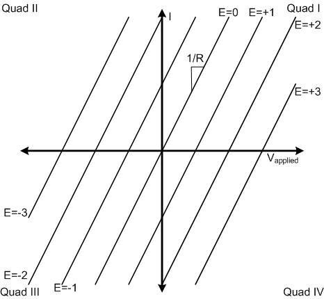
Like Skogs, I found the plot you showed more confusing than explanatory. I decided to create a plot that shows the principle in the more traditional, and I believe clearer, format.

Four_Quadrant_Drive_Plot_te4rfx.jpg


The key difference is that the horizontal axis is the (signed) voltage applied by the drive, not the motor back EMF. The vertical axis is still the resulting (signed) current.

The diagonal lines are constant (signed) back EMF values. (Don't worry about the units - it's the concept that's important.) So go left or right to get to the applied voltage, then go up or down to get to the back EMF, and you get the resulting current, and you see what quadrant it's in.

At root, all this plot is showing is the equation

I = (V - E ) / R

where V is the applied voltage, E is the back EMF, and R is the resistance. (We are ignoring the transient L*di/dt term here.)

Quadrants I and III are motoring; quadrants II and IV are generating.

I hope this is a lot clearer. You should still take Skogs' advice and study some good references for a deeper understanding.

Curt Wilson
Omron Delta Tau
 
Many thanks cswilson for the nice chart. I have a question: wg=hat does it mean physically that back EMF and applied voltage are opposite. You said in your first reply that "If the applied voltage is of the same sign as the back EMF voltage and of lesser magnitude, or of the opposite sign, you are generating, converting mechanical power to electrical power.".
Thanks in advance
 
In normal operation, the difference between the applied voltage and the back EMF is small.
The effective armature voltage is the difference between the applied voltage and the back EMF.
This is so important that it bears repeating.
The effective armature voltage is the difference between the applied voltage and the back EMF.

mawad said:
or of the opposite sign
This is best explained by an example.
For example let's consider a motor where the difference between the applied voltage and the back EMF is 5 Volts.
There may be conditions where one sign is positive and the other sign is negative.
For example: difference = 5 Volts, applied voltage minus 3 Volts, back EMF positive 2 Volts.
Different signs do not imply a great difference in voltages and does not imply an abrupt reversal of one of the signs.
Another relationship:
The armature current is closely related to effective resistance of the armature circuit and the difference between applied voltage and back EMF.
The armature current is also closely related to the torque on the motor, whether driving or driven.
Consider a motor running at a given speed:
The applied voltage is increased.
The effective armature voltage is increased. (That is the difference between the applied voltage and the back EMF)
The current and the torque increase.
The motor accelerates.
The motor speed stabilizes at a new higher speed.
This is a dynamic, changing relationship which is dependant on the speed, the applied voltage and the torque.
A graph can not illustrate these dynamic relationships.
A two dimensional graph may illustrate two variables only.
A graph may be able to illustrate motor action if one of the variables is stated as fixed, however, that is seldom the case in the real world.


Bill
--------------------
"Why not the best?"
Jimmy Carter
 
Successwale, you posted this response in the wrong thread!
 
mawad:

Let's look at the two armature terminals, which we'll call U and V. With an active rotor magnetic field of a given polarity, applying a voltage across the terminals will generate current and torque.

Let's say the voltage on U is greater than the voltage on V, and we call this a positive applied voltage. With no load torque, this causes the motor to spin in a direction we will call clockwise.

If the voltage on V is greater than the voltage on U (negative applied voltage), this causes the motor to spin counter-clockwise.

Next, with the armature terminals open circuit but measuring across them with a voltmeter, and with the same rotor magnetic field, spin the motor up mechanically clockwise. You will see the voltage on U greater than the voltage on V. This is the back EMF voltage of the motor, positive in this case.

If you spin the motor mechanically counter-clockwise, you will see the voltage on V greater than the voltage on U -- a negative back EMF.

Now, look at an instant when the motor is spinning clockwise. It does not matter what caused it to spin this direction: applied external torque, applied current, or some combination. It will have a "positive" back EMF as we have defined it here. We use our drive to apply a higher voltage to terminal V than terminal U -- a "negative" applied voltage.

Consider a specific example. The motor is spinning clockwise at a speed that produces a +20V back EMF. We apply a -10V voltage across the terminals with our drive. This creates a current I = (V - E) / R = (-10 - 20) / 5 = -6 amps for a 5-ohm armature resistance.

This is significantly different from the case where we apply a +10V across the terminals. There we would get I = (10 - 20) / 5 = -2 amps.

Of course, you must understand waross' point that the currents create torques that change the speed and therefore the back EMF, so the solutions are constantly changing -- you really need differential equations to understand the behavior over time. But this is a start.
 
Status
Not open for further replies.

Part and Inventory Search

Sponsor