Continue to Site

Eng-Tips is the largest engineering community on the Internet

Intelligent Work Forums for Engineering Professionals

  • Congratulations SDETERS on being selected by the Eng-Tips community for having the most helpful posts in the forums last week. Way to Go!

BTH-1-2014 Shear ? 2

Status
Not open for further replies.

ColinPearson

Petroleum
May 1, 2011
142
Hello folks!
It's been a long day in an already very long week and it's only Monday so maybe some sleep would help, but I have a question about ASME BTH-1-2014 Eq 3-37. It's turned up before on the forum but not really in a way that answers my questions. Really, I think I jsut need a little hand-holding here...

fcr = SQRT( fx^2 - fxfy + fy^2 + 3fv^2) <= Fy / Nd EDIT: original post said "+ fxfy", fixed here

where:
fx = computed normal stress in X direction
fy = computed normal stress in Y direction
fv = computed shear stress

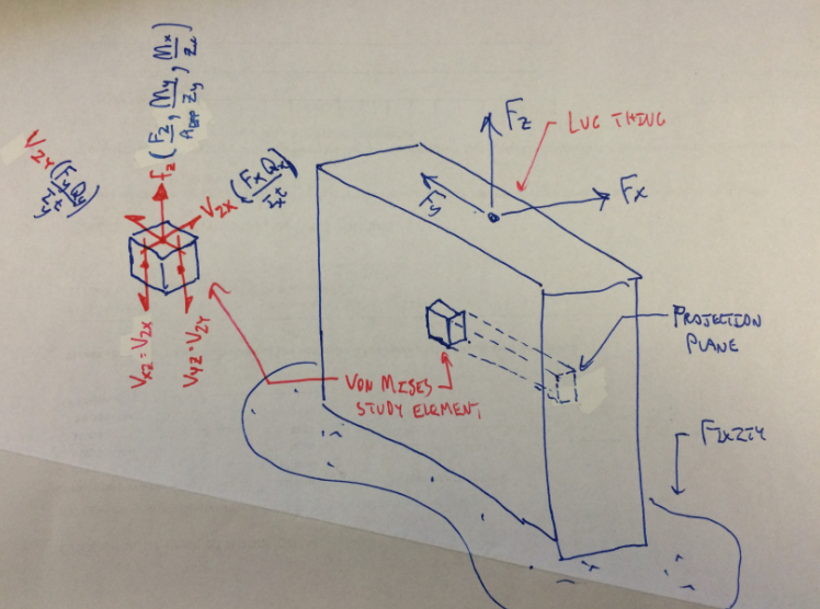
Now... say my XY plane is "flat", and I've got forces Fx, Fy and Fz. Let's say further that all forces act at some moment arm such that there are bending stresses induced by all three forces. Now, I would consider the compression and tension resulting from those bending stresses to be acting normal to the XY plane, but wouldn't you say they acted in the Z direction? I'm confused when the explanation of the variables offered by ASME talks about the normal stresses in both the X and Y directions; do they mean the normal stresses caused by the forces acting along X and Y? I'm looking at BTH-1-2014 Chapter 3-2.5; same chapter for the 2011 version.

Thanks in advance, cheers! (sketch attached)
 
 http://files.engineering.com/getfile.aspx?folder=4dfcf14a-e2d6-4004-b145-3d6cfeb4e19d&file=HELP!.pdf
Replies continue below

Recommended for you

If I'm not mistaken that the Von Mises general plane stress equation:
66c4a0a511ba04f23d051040ac465315.png

Thus it should be your stresses in the Fx, Fx, Fz direction, matching your same coordinate system for your loads.

Professional and Structural Engineer (ME, NH, MA)
American Concrete Industries
 
It's interesting because it was wrong; corrected and thank for the catch.

Bear with me here if you would TehMighty, but I'm not quite up to speed. The subscript on the final term is "v" in BTH-1 ("12" from your source) and they define as "computed shear stress". Obviously the symbols used don't particularly matter, but that to me would seem to include shear sress induce by Fx, Fy and Fz (torsional in my case), is that incorrect?

I'm also still confused because the forces Fx and Fy (in my case) are in the same plane as the shear stress and therefore I'm not following where the "normal" part comes in - I would have thought that normal stress referred to the bending (about the XX and YY in my case).

Any thought? and thanks for taking a minute to respond!
 
Bear with me as I haven't had my coffee yet and might not explain this correctly.

σ12 (or fv) should be the in-plane shear stress by my understanding. So you have Fx & Fy being the in-plane stresses due to axial forces, and Fxy being the shear stress in the X-Y plane.

Thus, your Fx and Fy should be in the same plane as your shear force (Fxy).

I'm sure there are better references but the one I always end of using (usually because I'm using the FEA feaures) are the help files of RISA and STAAD (when I was still using it) which have nice little graphics showing these stresses:

download.aspx


Professional and Structural Engineer (ME, NH, MA)
American Concrete Industries
www.americanconcrete.com
 
It's worth noting that I'm not an expert in plates and shells and only know enough to squeeze by and be dangerous. ;) I'm sure someone could explain this better than I can.

Professional and Structural Engineer (ME, NH, MA)
American Concrete Industries
 
I am not even halfway through my first cup, so I hear you!!!

I am with you partially and agree that I've indeed got shear stress due to Fx and Fy that lie in the XY plane. In addition, I've also got torsional shear stress to to a moment/torque about the ZZ axis. The way I'm reading it, the SHEAR stress induce by Fx, Fy and Fz should all be combined in that final "fv" term.

The thing that is really hanging me up is where the "normal" part comes in? This is the equation for analyzing "Combined Normal and Shear Stresses", but as far as I can tell here, there's nothing in Eq 3-37 that's acting normal to the XY plane where my shear stress lives. Now, you did say that I "have Fx & Fy being the in-plane stresses due to axial forces" which I am not quite grasping; I would call Fz and axial force here, but not Fx or Fy. And, obviously, Fx and Fy are normal to each other, but I take this equation as referring to a force/stress acting normal to the plane where the shear lives i.e., as a way to look at the combined effect of bending or axial stresses together with shear.

I hate to beat this horse so badly, and I hope I'm not being a drag here, I'm just not quite there yet. Thank you kindly for your help.
 
Sorry, by axial forces I meant "plane stresses in the x and y axis". They're all technically axial forces but, yes, they are not your longitudinal axial force.

I think by "normal" they mean stresses normal to the faces of the element being analyzed. So, if we define some discrete element by cutting it out of a larger piece then you have 6 faces on the element (as shown in the pictures above). The Fx, Fy, and Fz stresses are all "normal" to these cut faces.

Professional and Structural Engineer (ME, NH, MA)
American Concrete Industries
 
Your trouble here stems from attempting to use the 2D Von Mises failure criterion on a 3D stress problem. Google "Von Mises 3D" and you'll get the idea.

I like to debate structural engineering theory -- a lot. If I challenge you on something, know that I'm doing so because I respect your opinion enough to either change it or adopt it.
 
KootK has it, and that's what I was missing. I didn't read your problem statement fully and was trying to explain only your equation as written. If you have 3D stresses then this gets a lot more complex and is probably beyond me. Short answer is you cannot use the equation as written.

My understanding is you will have to revert to the full Von Mises yield criterion equation:
a4b19942b0444f0e147e84ccf1edf189.png


Professional and Structural Engineer (ME, NH, MA)
American Concrete Industries
 
KootK, I actually have, and it's a reminder of some basics that I need to brush up on for sure!

That said, unless an object was ONLY loaded in (say) the X and Y directions, then I don't see a way that I would have shear stress AND stress normal to that plane. I would think that one would need some axial (tension/compression) or bending moments about those XX and YY planes to induce shear AND normal stresses. That said, the equation is just sitting there to use without a huge amount of clarification. If you look at my sketch, if I were to constrain Fz to lie ALONG the Z axis thereby eliminating the moment about ZZ-axis and the resulting torsional shear, do you feel like that equation 3-37 would more aptly apply to that situation? How would that Fz ever end up having an affect on the equations results?

I feel like maybe the issue is a bit wider than the intended application of the equation; I'm trying to understand what I should do to correctly apply the intent of the check in a situation where the given equation may not exactly apply to. Thanks again!
 
Kind of what I was thinking that y'all were driving at TehMighty and KootK. How have you approached something like this in your work when the prescribed equation doesn't really fit the situation, but it is what it in the code? I know that equations are not magic bullets and they only apply for given sets of criteria, within limited ranges, etc, but I'm not sure how to proceed when it seems liek the prescribed equation doesn't describe the situation accurately.
 
My gut feel here is that the effect of Fy will be negligible and can be neglected, taking you back to the 2D equation applied to the XZ plane. Of course, you're relieving advice from a guy who doesn't know your loads, proportions, or boundary conditions. So proceed with caution.

I like to debate structural engineering theory -- a lot. If I challenge you on something, know that I'm doing so because I respect your opinion enough to either change it or adopt it.
 
If I'm fairly clear on the intent of the original equation (in this case a Von Mises yield criteria) then I usually adjust it as I feel is appropriate. If I'm not clear than it's off to eng-tips, senior engineers, and/or the governing body of whatever specification I'm referring to.

Professional and Structural Engineer (ME, NH, MA)
American Concrete Industries
 
KootK: Let's say that my XY plane is "flat" ( I guess ALL planes are flat!) and it represents some structure or other thing that a lifting lug would be welded to. For ease of imagination, let's say our XY is overhead. That means that Fz would be vertical and as you'd guess, that would be the direction of loading due to the weight suspended from this lug. I'm working on a super-spreadsheet to design and/or analyze existing lugs so I'd like the ability to have the load apply anywhere along a 180deg path i.e., 100% along +Y to 50%/50% between Y and Z (45 deg), 100% Fz (90deg) and so on until all the load is in the -Y direction. In addition to that, let's consider 'sidepull' to act in the X direction, so I'm including a max out-of-plane loading angle of something like 5deg-10deg. As you can see, I've got a real interest in the 3D problem; even the small amount of sidepull is of interest because a) it happens in real life all the time, and; b) it's against the weak axis and therefore worth being mindful of. Hope that clears up what my intent is.

TehMighty: Thanks for your input. I'm actually drafting an interpretation request to ASME BTH about the question now.

Thanks folks!
 
Can you just ignore some of the plate so that there is no torsion? Just neglect enough of the plate on the left side so that your force is at the centroid
 
Possibly, yes, at least when we have design control, but I would like the option to leave it in the spreadsheet. In practice, I've seen a lot of lugs that have the hole significantly eccentric w.r.t. the lug centroid. Say, for instances where the weld needs to be pretty long, then you can either have a much taller lug and taper it up from the base to the pin hole, OR, you can keep the lug fairly shallow in height but offset the hole way to one side so you still have appropriate clearance for rigging hardware to attach. In a straight pull situation, that is fine, but if you're a few degrees off straight and a foot or so off of the centroid, I'd like to leave the torsion in there.
 
In practice, whenever I've had to do something like this I would resort to a FEA computer model to calculate the Von Mises stresses rather than try to build a spreadsheet that covers all the bases. Generally it ends up taking a little more time in total but the added flexibility of a 3D FEA program is quite useful and generally easier to review as well.

Professional and Structural Engineer (ME, NH, MA)
American Concrete Industries
 
Well, I've got Inventor and a pile of books about it's use and an additional book and online lecture series I bought specific to the FEA capabilities, so that's one thing I'm learning right now. I very well may just leave that stress as a user-entered value to be determined in an FEA. Good idea.
 
Working out the demand side of the 3D Von Mises check is certainly doable. Personally, I wish that codes wouldn't micro manage the design process by specifying stuff like this explicitly. Based on what I know of your system, the real issues will be effective flexural/buckling width, bi-axial flexural stress, and cantilevered plate buckling. I doubt that shear is even worth checking except, perhaps, locally at the hole as bolt tear out etc.

Capture01_tq2nl3.png


I like to debate structural engineering theory -- a lot. If I challenge you on something, know that I'm doing so because I respect your opinion enough to either change it or adopt it.
 
Status
Not open for further replies.

Part and Inventory Search

Sponsor