Continue to Site

Eng-Tips is the largest engineering community on the Internet

Intelligent Work Forums for Engineering Professionals

  • Congratulations KootK on being selected by the Eng-Tips community for having the most helpful posts in the forums last week. Way to Go!

FFWs used in all directions? 1

Status
Not open for further replies.

DGrayPPD

Mechanical
Feb 2, 2017
300
Hi,
I was wondering if I could get the opinion of some more senior level experienced people. I am a piping designer that works for a small engineering firm who is trying to expand in the field of detail engineering. I am a certified Level II SPED piping designer. I have a background in pipe fabrication shop spool drafting and now in piping design and through my years of experience, education, and the countless research I have done, when it comes to FFWs my understanding is that you do not want to put an excessive amount and they should only be used in times of absolute uncertainty, between equipment in parallel, or for a final fit up to equipment like pumps who can not have an excessive load on the nozzle. Unfortunately, because we are a small engineering firm, I do not have any senior level piping designers/leads to back me up on this. And our other engineers believe that it is beneficial to have FFWs in every direction for most lines. They have tried to convince me to put them and I have held my ground and told them it is not necessary to put an excessive amount of FFWs. It is my understanding that this could greatly influence the budget and schedule of a project. They're opinion is that how many times have you seen contractors build the plants exactly where we told them to which my rebuttal is why are we designing it and giving them location plans, equipment plans, isometrics, 3D models, etc., if they are not going to build it where we told them? I know they have tolerances in the field, but is my thinking wrong on this matter? Can anyone give me their thoughts and opinions?
 
Replies continue below

Recommended for you

Yes, that is one of many articles I have read lol. I don't know that there are anymore articles for me to read, as I feel as though I've covered them all. I just wanted some senior experience on the issue.
 
I'm not sure how to define "an excessive amount of FFWs".

You will (obviously) necessarily have FWs for straight runs longer than double-random so you can handle one or more planes' adjustment there. Much will depend on site erection considerations like perhaps threading pipe into multi-level racks or other obstructions but these may be issues handled by your contractor depending on contract details. Many designers will just include a FFW in 3 planes and leave final placement decision up to the field.

Is this for a specific project where you have detailed knowledge of the facility to be built/upgraded or a general question?

 
DGrayPPD said:
"Having a Field Fit Weld in all 3 planes on just about every line"

I'm not sure I understand this completely. Could you provide a sketch?
 
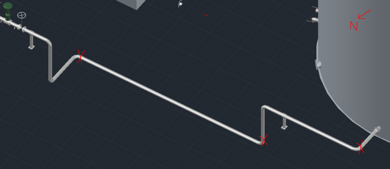
For example, in the image below, some engineers here believe that a field fit weld (6" of extra pipe) should be provided in all 3 planes where I have indicated with an X, instead of just a regular field weld (no extra pipe). The first in the E-W plane, the second in the vertical plane, and the third in the N-S plane. However, it is not for just this pipe that they feel this way. They feel as though there should be a FFW in all 3 planes for just about every line of pipe. From what I have read this seems to be a bad practice and would require extra man hours for a construction crew to have to measure, cut, bevel, and weld nearly all spools. I just want a second opinion though.

FFW_yidzia.png
 
DGrayPPD,
Again, I am on your side on an issue.
There is a time and a place for everything.
An FFW adds work and therefore adds cost to the project. Consider some examples: A 3" sch 40 carbon steel line with 3 FFW's. Or a 24" sch 160 Stainless Steel with 3 FFW's. Think about the details involved and the real cost. FFW's should only be used in cases where the project Pipers know they will be needed and excessive FFW's should be avoided.

Sometimes its possible to do all the right things and still get bad results
 
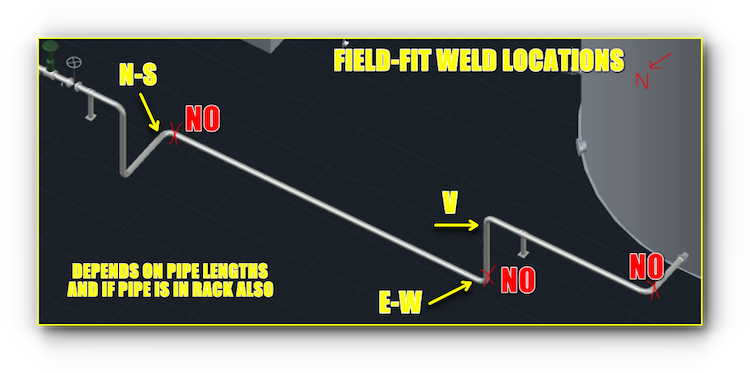
Don't forget that you will have "natural" break points needed so as to fit spool assemblies within the shipping envelope that can also be used as FFW locations. I would move your FFW locations to where I've shown below, based on what's presented in your screen capture.

My criteria was to maximize spool dimension and locate welds in accessible locations. There will be differing opinions on "best" locations, that's why it's often left to the erection contractor.

And of course, modularization solves many of these FFW issues.

FFW-LOCATIONS_uzxhbe.png
 
I'm going to disagree with you there.
The very long section in the middle should be the field fit (its long leg cut extra long since that is spanning a section between tanks that is very likely to be off. (long or short.) The elbow going to it should be in the first spool, since the long straight will accept a significant degree of offset in all directions (as long as drain criteria is met - but you have no provision that in the spools anyway.)

Only one vertical field weld?
 
So, when you say, "every line of pipe", you mean a complete line number from origin (equipment or other pipe system) to destination and not sub-assemblies of pipe and fittings.

In many ways, specifying 3-axis FFWs for each line number provides a certain amount of "wiggle room" for the designers but as pennpiper notes, this can get very expensive for large bore / heavy wall / exotic materials.

Some companies offer dimensional control services using scanning technologies that aim to reduce the need for FFWs. Here's one:
 
Yes, each complete line number from origin to destination.
 
I would like to introduce a related issue with this Original Post (FFWs used in all directions?
Almost all people including Pipers define FFW as Field Fit Weld. I have tried for years to get people to make a change to this definition.
I think it should be "Final Fit Weld".
With the current practice of FFW (Field Fit Weld) and "Field" being included in the Specifications and/or Sub-Contractor Instructions there is no direction given as to when "that" weld should be made.
I submit that the FFW (Final Fit Weld) should be the definition and the instructions should clearly define "that" FFW as being the Last (or Final) weld for that Line.

Without that change and clear understanding of the intended timing for the performing that weld you can find yourself at the mercy of an unscrupulous Sub-Contractor.

Consider this Hypothetical situation:
A line is a long complex configuration with 4 Isometrics. The Line is a 6" pump discharge from P401A and P401B, joining under the Pipe Rack(PR) at 12'-0" before entering the lower (15'-0") level of the PR and turning North 30'-0". Next the line has an Orifice run that covers a full bay (about 30'-0"). Then the line travels one additional bay and drops down out of the PR. The line then crosses(14'-0") under the PR (at the 12'-0"elevation) and drops to near grade and has a full Flow Control Valve (FCV) Station. The Line then rises back up to the 12'-0" level, travel to the Process Equipment row and turns up, and rises to a Nozzle near the top of the 180'-6" Fractionation Column.
(Note: the configuration of this fictional line is not intended to make sense.)
Now:
1. How many FFW's do you think are required and where would you place them?
2. What if the Sub-Contractor bevels the end of that 9" (extra length). No measurement just Bevels the End and weld it to the next Spool. Later when the last Spools were placed they do not fit, they are all 9" out of alignment.
3. You say they did not do it right, do it over again.
4. They say you never told us anything about when we were to make that "Field Fit Weld.
5. It went to arbitration and the Sub won. They got paid 3 times, once for doing it the first time, then paid for taking it out and then paid again for doing the third time to get it right.
6. That it why I think the first "F" in FFW should be "Final" and there should be strong wording as to when and how the "FFW" is made in the Installation Instructions/Specifications.
7. Think about it!

Sometimes its possible to do all the right things and still get bad results
 
Interesting hypothetical scenario. I could see it possibly happening on a large project with a "certain" type of contractor and poor/inexperienced supervision. And it could be difficult to forensically determine after the fact what actually happened in some circumstances.

2. FFWs should be plain end, though, with a scribe line indicating where the theoretical field cut and field bevel location is.

I agree that this sounds like a good idea.

Paul

PS I specifically asked for the definition of "Having a Field Fit Weld in all 3 planes on just about every line" because I've seen cases where a line spanning multiple piping isometrics contained more than one FFW in each plane. The instruction was misinterpreted as meaning each isometric was to contain a FFW in each plane.
 
Let's use a heat exchanger for example. You have 4 nozzles (2 shell side, 2 tube side). The 4 pipe lines running to and from the exchanger nozzles would all require 3 field fit (or final fit) welds in all 3 planes (N-S, E-W, up-down) for a total of 12 FFWs if the method described above is followed. Seems excessive and unnecessary to me and a complete waste of construction man hours when there more than likely would not be an issue for the contractor fitting the spool pieces together
 
Status
Not open for further replies.

Part and Inventory Search

Sponsor