Continue to Site

Eng-Tips is the largest engineering community on the Internet

Intelligent Work Forums for Engineering Professionals

  • Congratulations waross on being selected by the Eng-Tips community for having the most helpful posts in the forums last week. Way to Go!

T beam width flange

Status
Not open for further replies.

yaroosh

Structural
May 11, 2015
32
Hello Everyone,

I hope I am posting my question in the right place.

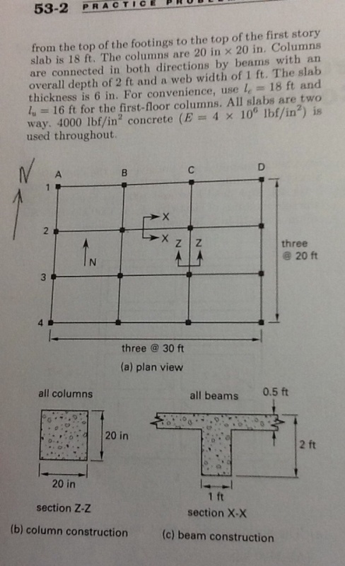
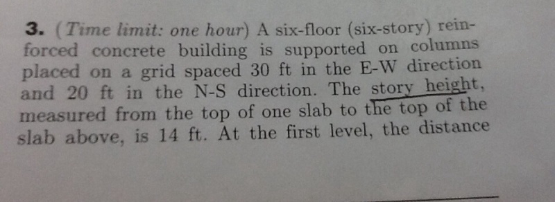
I am solving a problem in Linderburg for reinforced concrete slender column chapter. He is using in one of the questions a two way slab- t beam with the effective flane width unknown. Per aci 8-11, the effective flange width shall be minimum quarter span etc... However, he is determining the value based on isolate beam criteria. I don't quite understand why. I am thinking of isolated beam in a literal sense as it is isolated unless there is something I do not understand. I will truly appreciate if someone can clarify to me why he is using isolated beam criteria. I know this might be simple for many but not for me yet.

Thanks a lot.

 
Replies continue below

Recommended for you

Is the beam being checked at a negative moment location where the T-beam flange is in tension?
 
No the beam is checked at midspan. Does this make a difference?
 
Could you post a scan of the question? I'm confused why it's T-beam design the the slender concrete column chapter.

Different assumptions are made when concrete T-beams have the flange in compression versus the flange in tension.

I like to debate structural engineering theory -- a lot. If I challenge you on something, know that I'm doing so because I respect your opinion enough to either change it or adopt it.
 
getfile.aspx
image_ljt29g.jpg
image_of1zrd.jpg


Kootk here are the pic. Thank you so much for your help.
 
Thanks, that helps some. Could you also post the parts of the problem that include:

1) The statement of what is being asked?
2) The parts of the solution where the tee beam is being addressed?

It does appear that the question concerns slender column design procedures. As such, the author may have used the non-flange properties of the tee beams to make a conservative estimate of rotational restraint at the top of the column. The code tee beam flange provisions are really intended for the flexural design of the beams themselves rather than the design of other elements.

OP said:
No the beam is checked at midspan.

This still throws me off. What exactly is being checked at midspan of the beam? Again, posting the details of the solution would make it easier for us to parse the intent.

I like to debate structural engineering theory -- a lot. If I challenge you on something, know that I'm doing so because I respect your opinion enough to either change it or adopt it.
 
I
image_ie0jme.jpg
image_ypwynf.jpg


I apologize for my late reply. Here are the pic. Thank you again for your help.
 
I think you are getting confused because there are two seperate problems here, that appear unrelated. If you are not confused, then I surely am :-)

image_reau5o.jpg


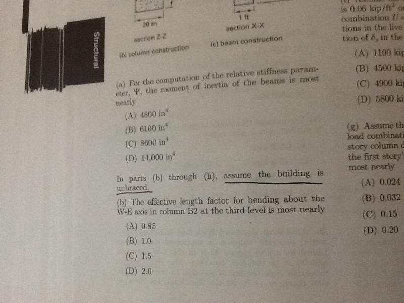
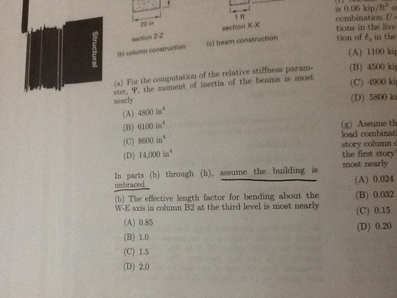
First, the above question (a), as it states, ask you to calc the beams moment of inertia, I, as part of the Jackson and Moreland Alignment Chart of ACI 318-11 §R10.10.1.1.

Assuming rectangular beam dimensions of a 24" deep x 12" wide beam the Ig is 12x243/12 = 13,824 in4.

If you assume a T-beam, with an effective flange width of 60" (1/4 of 20' span) then Ig is = 26,352 in4.

If you assume a T-beam, with an effective flange width of 90" (1/4 of 30' span) then Ig is = 29,669 in4.

If you assume a T-beam, with an effective flange width of 48" (the effective flange given below) then Ig is = 24,470 in4.

However, you have to reduce the stiffness to account for cracking, so as per §10.10.4.1(b) you multiply by 0.35 to get an effective EI.

Based on the "most nearly" available answers 0.35 of 24,470 is 8,565 or "most nearly" 8,600 in4.

So assuming C is the correct answer, the solution is based on a 48" wide effective flange. Maybe check the worked solutions to see if the author states why 48" was the selected effective flange, and not 1/4 of spans, or 16t+b etc.

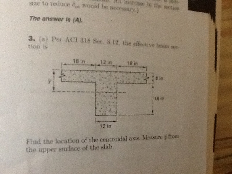
I originally thought the other question was a standalone T-beam calculation, with GIVEN effective flange dimensions, and not related to the above problem, and it wants you to calc the position of the centroidal axis, measured from the top of slab.
image_xdp1xo.jpg

I calc that is ÿ = 8.14 in.
 
Status
Not open for further replies.

Part and Inventory Search

Sponsor