Continue to Site

Eng-Tips is the largest engineering community on the Internet

Intelligent Work Forums for Engineering Professionals

  • Congratulations The Obturator on being selected by the Eng-Tips community for having the most helpful posts in the forums last week. Way to Go!

Increasing negative moment flexural capacity via upturn concrete 1

Status
Not open for further replies.

Ingenuity

Structural
May 17, 2001
2,360
I have existing (30+ year old) 2-span PT beams (5'0" deep x 2'6" wide) that requires significant strengthening over the interior support (negative moment) for additional loadings for a proposed roof recreation deck.

The upturn can be integrated into the completed rec deck as a new pedestal system (of several feet in height) will be provided.

I have used ACI 318-14 to check horizontal shear transfer (composite action of existing beam to new CIP upturn) for a magnitude equal to the total tensile capacity of the added rebar.

I checked interface shear and shear reinforcing is required, via shear-friction across an intentionally 1/4" magnitude roughened joint of 24" width.

I have used only #3 reinforcement to assist with a reduced straight bar development lengths (ld=12" for #3) into the existing concrete (via epoxy etc), and #3 also results in a reduced hooked development length (ldh=6.5" for #3) above the interface.

I would usually detail a third row of reinforcement down the centerline of the beam (across the 24" upturn width), HOWEVER, there is existing PT tendons that I wish to avoid drilling through, so I only have 2#3 over the 24" width.

Any thoughts/comments of the following detail WITHOUT a center row of #3 interface reinforcing?
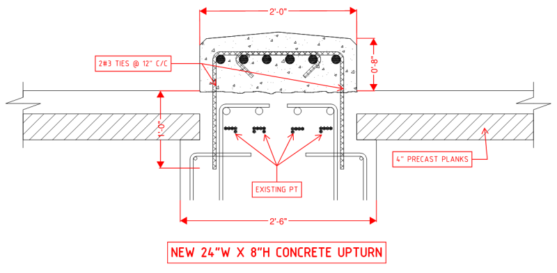
UPTURN_2_etehzc.png
 
Replies continue below

Recommended for you

I don't see a third leg being needed in negative moment areas where the new bars are in tension. Locating the dowels might be tricky. You not only want to avoid the PT but also the existing stirrups. The stirrups are needed the most in the negative moment areas. It might be worth digging down occasionally to locate the existing stirrups to confirm their width.
 
With shear friction, doesn't the bar need to be developed on either side of the joint? Will that be possible given the edge distance to the precast planks?

All of your post tensioning has already been installed, so while this will put the existing concrete into compression, there's no way for that force to be transferred across this joint - either with or without shear friction. Are your top bars being designed for the entire negative flexural load? Or are you assuming some sort of load sharing between the existing beam and the new reinforcement?
 
cooperDBM and Once20036:

Thanks for your comments. I will use just 2 rows of dowels.

cooperDBM said:
It might be worth digging down occasionally to locate the existing stirrups to confirm their width.

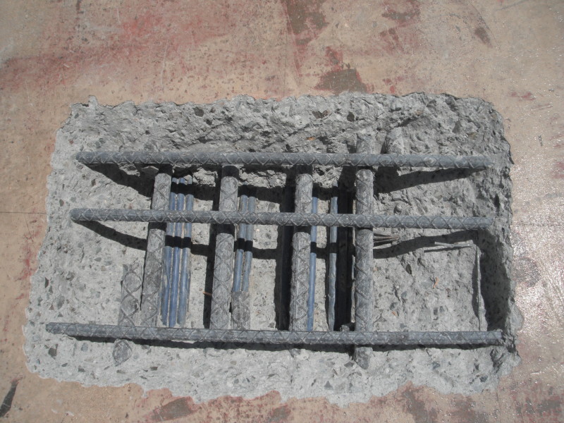
We have done one invasive probe (see below) and plan on a few more probes, following GPR scanning of the areas.

DSCF6191_yfunln.jpg


Once20036 said:
With shear friction, doesn't the bar need to be developed on either side of the joint? Will that be possible given the edge distance to the precast planks?

Yes, the #3 shear dowels will need to developed both sides of the roughened joint - which for 5000 psi concrete works out to be 12" for straight segment, and 6.5" for the hooked segment.

The precast plank bears within the CIP beam by 3", and the #3 dowel hole will be approx 2" from the edge of plank, or 5" from CIP side face, which I think will exceed edge distance requirements.

Once20036 said:
All of your post tensioning has already been installed, so while this will put the existing concrete into compression, there's no way for that force to be transferred across this joint - either with or without shear friction. Are your top bars being designed for the entire negative flexural load? Or are you assuming some sort of load sharing between the existing beam and the new reinforcement?

Yes, all the creep and shrinkage effects have practically taken place, so we are disregarding any P/A from the existing PT and expect the upturn concrete to be flexurally cracked with distributed cracks.

We are effectively looking at the ultimate moment condition. Actually, there is a back-story here. We have been engaged by the GC. The EOR has detailed the strengthening incorporating all NEW rebar within the existing concrete section - so extensive concrete chipping to top of beam, then place the NEW rebar under (grrrr!) the existing #6@6" top slab rebar and beam stirrups, then patch back. Our effort is to replicate/match the NEW ultimate flexural capacity (based upon the EOR's method of strengthening) by using the NEW bars within the NEW concrete upturn.

I have not yet checked the CURRENT negative moment demand - probably just beam SW, plank and topping SW, some misc construction LL etc - but the FINAL NEW flexural demand (and what I expect the NEW bars will be primarily taking) will include new superimposed DL and large portion of new LL.
 
In my opinion, interface shear is the wrong way to go about this. Rather, the problem at hand is the fundamental detailing requirement for your shear reinforcement (existing) to make it to your tension reinforcement (new). Without that, our truss model of concrete shear is shot. Naturally, there's a horizontal shear concern as well but, with the vertical shear properly resolved, the horizontal should be self solving as it is in monolithic concrete.

The form of the solution would be similar save a few modifications:

1) you'd need to provide dowels for the peak shear demand rather than averaging the demand over the length of the reinforcing bars. Just as with normal stirrups.

2) you'd need to go deeper with your dowels as the goal is to not merely develop them but, rather, to lap them with the existing stirrups as extensions of those stirrups.

3) You could get away with just standard 135 corner hooks at the tops of the dowels as we do with other stirrups. Perhaps a little more constructible. I still favor some candy canes across the top, however, to help with tension load spread across the width of the beam. Cheap insurance and you'll need carry bars anyhow.

As for the centre row of interface dowels, I would argue that they would be largely pointless unless there was an existing stirrup leg in the middle for the dowels to lap width.

For what it's worth, I see no reason why the prestress cannot be assumed to help with ultimate flexural strength in this situation.

I like to debate structural engineering theory -- a lot. If I challenge you on something, know that I'm doing so because I respect your opinion enough to either change it or adopt it.
 
KootK:

Thanks for your comments.

KootK said:
1) you'd need to provide dowels for the peak shear demand rather than averaging the demand over the length of the reinforcing bars. Just as with normal stirrups.

Agree. Using the "alternative method" of ACI 318-14 §16.4.5, we segmented the total "1/2" strengthened length into multiple segments and used the ΔM over each segment lengths (and therefore the corresponding ΔT in the rebar) to calculate the shear demand and calculate the required shear-friction dowels over each segment.

KootK said:
2) you'd need to go deeper with your dowels as the goal is to not merely develop them but, rather, to lap them with the existing stirrups as extensions of those stirrups.

I agree that a LAP length (not DEVELOPMENT length) is required under 'normal' conditions, but the beams have been already been strengthened for vertical shear over their existing 60" depth using FRP. So my thoughts (right or wrong?) are that if there is sufficient vertical shear capacity (based on the existing reinforcement plus supplementary FRP strengthening) then provided that the added NEW longitudinal rebar forces can be developed across the interface, then all is good. Lap splice length is only 1.3ld so maybe it is indeed best to drill and dowel a little deeper.

KootK said:
3) You could get away with just standard 135 corner hooks at the tops of the dowels as we do with other stirrups. Perhaps a little more constructible. I still favor some candy canes across the top, however, to help with tension load spread across the width of the beam. Cheap insurance and you'll need carry bars anyhow.

Our '2nd iteration' details amended the details to that posted above - changed longitudinal bars into 2 layers, and also changed the hook details, somewhat similar to what you suggested.

KootK said:
For what it's worth, I see no reason why the prestress cannot be assumed to help with ultimate flexural strength in this situation.

The prestress has been INCLUDED in the ultimate flexural strength/capacity. When I stated "disregarding any P/A from the existing PT" what I meant is that we are NOT calculating any elastic-based stresses, like the code requires you do when you place 1 kip of prestress!
 
Ingenuity said:
So my thoughts (right or wrong?)

Who the heck really knows? Not me. I'm pretty skeptical of shear reinforcing schemes that fail to directly connect the flexural tension and compression elements of the cross section. To the extent that it may be a legitimate a problem, it would be problem for both your dowel scheme and the shear reinforcing scheme. While I'm skeptical here, I'll freely admit that this isn't an area where I've got a 100% certainty myself. In fact, here's a thread of my own on nearly the exactly same issue: Link. I pretty thoroughly exhausted my capacity to over think things there so I'll mostly refrain from repeating that stuff here.

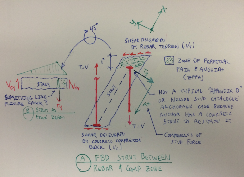
The sketch below is taken from that other thread. At the risk of tooting my own horn, I feel that I've now got a good handle on the mechanics in involved in partial height shear reinforcement. What I don't have is a robust way to say whether or not things are okay in any particular situation.

For what it's worth, I do recognize that FRP shear reinforcement commonly does not make it all the way across the section. That said:

1) It's usually taken as far across the section as possible.
2) You're stretching the partiality business a bit further than usual here.
3) I think that the situation is considerably more dire in the negative moment case than it is in the positive.

Capture05_s9uxtc_s51mny.png


I like to debate structural engineering theory -- a lot. If I challenge you on something, know that I'm doing so because I respect your opinion enough to either change it or adopt it.
 
Stumbled upon this in my travels considering your thing: Link. No specific point to makee; just sharing relevant info. Sounds like it works pretty well.

I like to debate structural engineering theory -- a lot. If I challenge you on something, know that I'm doing so because I respect your opinion enough to either change it or adopt it.
 
Thanks, KootK, for the follow-ups.

Your linked Nanni et al. paper on FRP resulted in Mu increase of about 40%, which is line with what I have done with FRP in the past.

The extended back-story with our project is that the EoR specified a FRP delegated design-build (based upon equivalent Grade 60 rebar), it went to bid and the winning FRP team came back with "no viable FRP solution" as the ductility was severely compromised given that they were trying to near double the flexural capacity.
 
Status
Not open for further replies.

Part and Inventory Search

Sponsor