Continue to Site

Eng-Tips is the largest engineering community on the Internet

Intelligent Work Forums for Engineering Professionals

  • Congratulations GregLocock on being selected by the Eng-Tips community for having the most helpful posts in the forums last week. Way to Go!

Twist in support beam - Remedies

Status
Not open for further replies.

Amar Yarli

Structural
Jun 12, 2017
8
Hi,

During one of the visits to site we have noticed a problem with the supporting steel work below the load cells for Support Frame. There is a clear visible deflection or twist in the top flange of the supporting beam and is likely to be increased when the vessels are fully loaded. Please see photos attached.
I have re-checked the calculations and can't see any problem. The beams are only 20% utilized (this is mainly due to restricting the supporting beam deflection to less than 1mm since load cells located on the beam and if any deflections on beam will effect the load cell readings)and the maximum deflections are less than 1mm (i.e. 0.31m).
We believe that the installers might have twisted the frames in the process of aligning them, but they claim this is not the case & beams have always deflected.

Could anyone please suggest any remedial measures ? adding stiffeners below the load solves the problem ?
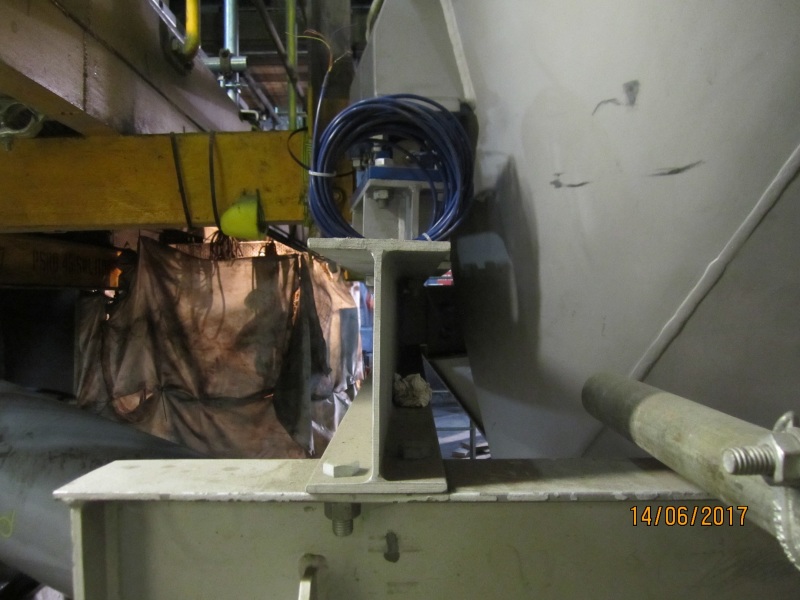
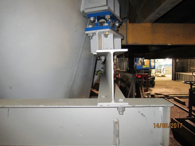
IMG_5860_hhnzht.jpg

IMG_5861_cdhrec.jpg
 
Replies continue below

Recommended for you

You can use transverse stiffeners at the end of the beam to provide rotational stability. That appears to be part of the issue. It also looks like the applied load is applied eccentrically. I would expect a twist under this condition.

Can you center the load over the beam?

 
I agree with bootl, the load eccentricity appears to be bending it.

Be good to eliminate the eccentricity.

I think it could do with stiffeners.
 
Beam under concentrated loads, besides the beam bending, shear strength and deflection check, following items may need to be checked too: flange local bending, web local yielding, web local crippling, web sideway buckling, web compression buckling, web panel shear, unframed ends of beams, and so on. The beam seems to have a pretty slender web, you may need to have a second look of the web related items listed above. And also the beam has unframed end, stiffener may be needed too.
 
yes, looks like eccentric load on the bm...the centerline of the lug on the vessel does not look like it lines up with the centerline of the support bm...as the vessel is loaded this eccentricity could increase due to local deflection in vessel and rotation of lug....
 
what is the dead load now @ the support lug and what will be the max design load ....unfortunately, I do not see an easy fix...the main support bm has a built up section on top fla that is orientated in a direction that should have been the main direction of the main bm...either that, or the lug location on the vessel was misplaced...anyway, below are some possible solutions:

1. remove built-up section on top of main bm and replace with bm(channel) in the same direction that
would span to 2 support points..provide these extra support points ,if necessary...

2. Add a pl to the inside of main bm from top fla to bottom fla for full length of bm...this would
move the centroid of the main bm inwards towards the vessel and also help with any torsion
present in the WF...not an ideal solution and may be difficult to get access to weld..

looking at the lug on the vessel, I would prefer a complete ring on the hopper located @ the bottom
of the lug to prevent local rotation of the lug....
 
Please post pictures showing how far from the ends of the twisted beam the load cells are mounted.


What kind of twist or eccentric loading are permitted by the load cell manufacturer?

I envision with the torsionally flexible I-beam, turning it into a "closed section" may be needed to keep the flanges parallel even after the we stiffeners are added.

An additional angled web stiffener from the point load to the end support might suffice.
 
Amar Yarli:
It does look like the lug on the hopper, the load cell and the bearing structure bellow it are loading the supporting beam a bit eccentrically. This could cause problems with the load cell and induce the twist/deflection you are seeing. I would lift the hopper intact, everything above the supporting beam. With plumb bob, vert. lasers, and the like mark the center of the load cell plane (or plane including two load cells, in each direction) on the top of the supporting beam and on the top of the larger beam/frame below. Then you will likely have to slot some bolt holes in the to of the support beam and in the top of the larger beam/frame, so the support beam can be slid in closer to the hopper. This should line things up. Also, you could install 45̊ corner stiffener beams (same size as the support beams, and approx. 3-4' long) from the web of the support beams, near the load cell support point, to the top flg. of the larger beam/frame. These would counteract some of the twisting you are seeing. It looks like the erector did not line the beams up very well with the center of the hopper lug/foot and load cell. You may want to look, and see, if you moved the whole hopper over .75" +/- left or right, would you fix the problem on the two parallel support beams, in one move?
 
Status
Not open for further replies.

Part and Inventory Search

Sponsor