Eng-Tips is the largest engineering community on the Internet

Intelligent Work Forums for Engineering Professionals

  • Congratulations waross on being selected by the Eng-Tips community for having the most helpful posts in the forums last week. Way to Go!

Steel truss gusset plate connection

Status
Not open for further replies.

rjmorton42

Structural
Nov 22, 2006
9
US
I am designing the connections for a simply-supported steel roof truss. The EOR specified the geometry, member sizes, and member axial forces. It is a Pratt truss with a configuration similar to this:
._______
/|\|\|/|/|\

The chords are WT sections and the webs are double angles that are lapped and welded to stems of the WT's. My question is at the bearing location at the ends of the truss (it bears on WF steel beams). The architect and EOR require a specific heel depth over the centerline of the beam, so the work point where the neutral axes of the WT chords intersect is ~16" outside of the centerline of the beam support.

My plan is to put a trapezoidal-shaped gusset plate welded to each side of the WT stems at the supports, and to add stiffeners directly over the support as needed. My questions is how to evaluate the gusset plates with the internal moment that results from this eccentric work point configuration. I have checked multiple resources, including all the AISC design guides, text books, and even Blodgett, and I can't seem to find a good discussion or example of how to look at this situation, but I know I am not the first person to run into this since I see it all the time in old buildings. Any guidance would be greatly appreciated.

Thanks!
 
Replies continue below

Recommended for you

I don't know why the end diagonal can't be sloped so that it intersects the bottom chord directly over the beam without eccentricity. A sketch might clarify the situation.

If you must have a 16" eccentricity for architectural reasons, the bottom chord must be capable of resisting a moment of 16R for the end panels of the truss. If the EOR has specified member sizes, he should have already taken the eccentricity into account.

BA
 
What you describe is a classic late 19th / early 20th century problem with steel trusses. The answer comes from history, 1909 specifically. A distinguished engineer, E.W. Pittman, wrote and presented a landmark paper (Secondary Stresses in Framed Structure) addressing solutions:

1. Use better details (than trapezoidal-shaped plates mentioned above) to avoid the problem.

2. In general, design gussets thicker so that they can be smaller... this makes gusset plates a better approximation of a pinned joint. Therefore, secondary stresses are lower.

Within ten years, or so, of the this paper's publication, the design of steel trusses was revolutionized. Improved gusset plate design largely displaced true pinned joints in steel trusses.

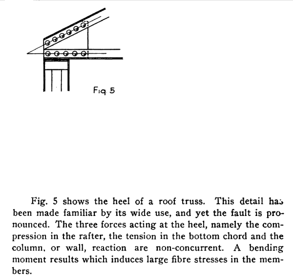
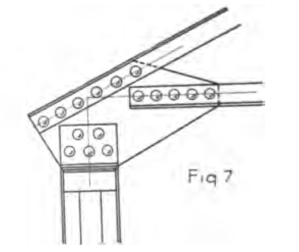
Figure 7, shown below, is probably a good detail for your use. The 1909 paper (PDF) is attached.

Note: Don't discount this paper because the joints discussed were riveted. The geometry is important, not the type fasteners (e.g. modern bolts or welds).

Figure_5-c_oymzie.png


Figure_7_-_Statement-c_hiuyoq.png


Figure_7-c_o7nu81.png


[idea]
[r2d2]
 
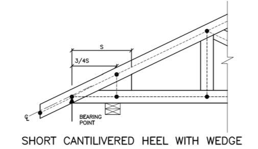
This is a pretty common EOR fail in my experience, both for steel and heavy timber trusses. Somewhat ironically, the metal plate connected wood truss folks do address this issue explicitly. They have what they call fictitious heel joint model analogs that deal with the eccentricity in a simplified fashion (clip below). I've applied that to heavy timber trusses in the past but haven't yet used it for steel trusses. The lack of a precedence for this in any of the steel literature makes me a little uncomfortable. And you usually need some extra "stuff" in the joint which can be a deal breaker for an exposed truss.

Here are my thoughts regarding your particular situation:

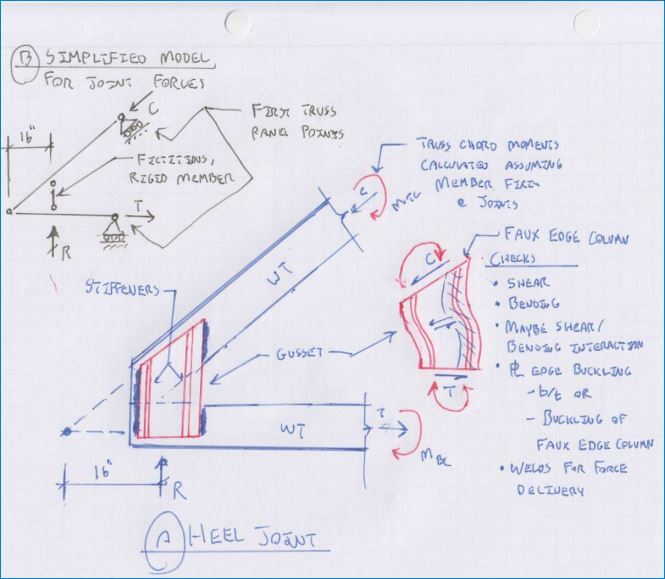
1) As BA mentioned, you'll have chord moments. In my opinion, they'll manifest in both the top and bottom chord in proportion to stiffness. I've shown a simplified method for estimating the moments below. It draws from the fictitious heel joint method that I mentioned above.

2) Before sinking to much time into your design, I'd query the EOR on the joint. Two things make me suspect that the EOR has failed to consider the joint eccentricity. Firstly, they didn't provide you with the moments that you need to design the connection. Secondly, a WT is a piss poor shape for the top chord in this application. The web of the top chord WT will be in flexural compression and will be unbraced between panel points. Not necessarily a deal breaker but, in my estimation, deserving of some attention.

3) I've proposed a design method for the gusset plate connection in the sketch below. This is just me making stuff up first principles wise. I know of no accepted reference that would explicitly support my proposal.

4) I love the stiffeners that you've proposed for the gusset plates. When you review my proposed method, you'll see why. It may not be the lowest cost approach from a fabrication standpoint but, man, does it feel good mechanically. I'd weigh the pros and cons of the particular situation. If there are 100 of these things, spend the time to design the stiffeners away. If there are two, keep 'em and move on.

Capture_3_zpfznt.jpg


Capture_2_giwm6h.jpg


I like to debate structural engineering theory -- a lot. If I challenge you on something, know that I'm doing so because I respect your opinion enough to either change it or adopt it.
 
Thanks so much for all the input. My configuration is essentially what SlideRuleEra and KootK show in their figures and sketches. My thinking was similar to what you both suggested, so I appreciate the confirmation.
 
Status
Not open for further replies.

Part and Inventory Search

Sponsor

Back
Top