Continue to Site

Eng-Tips is the largest engineering community on the Internet

Intelligent Work Forums for Engineering Professionals

  • Congratulations KootK on being selected by the Eng-Tips community for having the most helpful posts in the forums last week. Way to Go!

Plate Buckling 2

Status
Not open for further replies.

bootlegend

Structural
Mar 1, 2005
289
I have a situation where a 10" industrial walkway channel needs to be cut to allow head clearance for a walkway below. I think I have a relatively simple solution of welding a plate across the bottom as shown below to create a box type section. Yielding of the section should be no issue but I want to make sure the top plate doesn't have a buckling issue under compression due to bending. I used the AISC equations for bending in unsymmetrical members and used the critical buckling stress for a flat plate under compression as the Fcr in the AISC equations. I know the AISC equations are asking for the Fcr of the whole section, but the top plate would buckle first and so seems conservative to simply use the plate buckling stress.

My question is does this approach seem reasonable or is there some other more appropriate method I should use? By the way, I realize now that I should use the full width of the plate for the b value so that will result in a lower Fcr than shown.
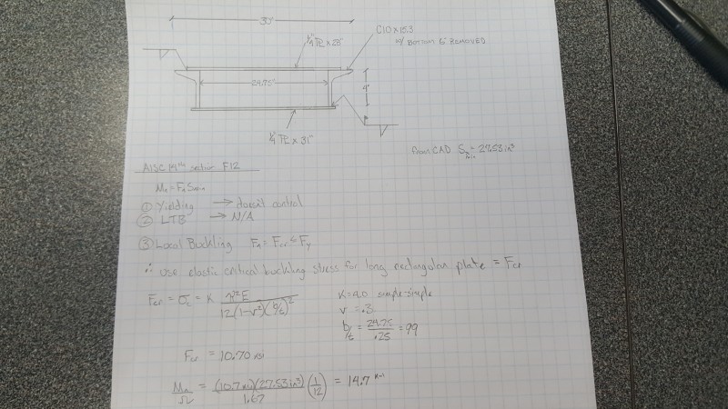
20171010_090912_wb3ud6.jpg
 
Replies continue below

Recommended for you

if it were I, I'd use an effective width of the plate, 30t at both weld lines.

I'd also suggest welding along the inside edge of the cut channel cap.

What's the compression allowable ? I doubt the channel cap will cripple. I don't know the compression allowable for a welded joint (if it had discrete fasteners then you'd have inter-rivet buckling).

another day in paradise, or is paradise one day closer ?
 
Can you apply the slenderness ratios specified in AISC for flanges, webs, etc? That strikes as the most "official" way to go about it.

I like to debate structural engineering theory -- a lot. If I challenge you on something, know that I'm doing so because I respect your opinion enough to either change it or adopt it.
 
@rb1957,
That was my first approach based off of the AISC effective width of flanges but then I was unsure of what to use for the allowable stress so I ended up here.
I'd also like to weld the inside but it would require overhead welding and I'd like to avoid that.

@KootK,
My first approach was to calculate the effective width for slender stiffened elements from the AISC equations. Simple enough, but when you get that value, is it as simple as calculating a new Sx off of that reduced section? I don't think the stress distribution would be linear so that doesn't seem right. Maybe the next step would be to calculate Zx for that reduced section and use Fy*Zx for the strength, but then how do I make sure that the local buckling isn't an issue? Does using the effective section ensure no local buckling? (I'm inclined to say probably but not necessarily.) Trying to find something to clear this up.

 
bootlegend said:
Simple enough, but when you get that value, is it as simple as calculating a new Sx off of that reduced section?

I think so. The stress distribution should be fairly linear assuming that your span is long enough for things to smooth out at the critical moment location. I've seen folks approach this kind of thing two ways:

1) Use the slenderness ratios to work out an effective reduced section that does not buckle when the other parts do buckle.

2) Use the slenderness ratios to work out a reduced allowable stress at which nothing buckles.

I favor #2 combined with an Sx design rather than Zx. When it works, it's pretty easy. I like easy.

I like to debate structural engineering theory -- a lot. If I challenge you on something, know that I'm doing so because I respect your opinion enough to either change it or adopt it.
 
RB1957's suggestion "if it were I, I'd use an effective width of the plate, 30t at both weld lines. I'd also suggest welding along the inside edge of the cut channel cap." has merit including welding on the inside edge... it insures that the plate is effectively fixed end condition at the channel part...

KootK's suggestion to use S in lieu of Z has merit since you are working in the elastic zone and your approach does not include for plastification.

Both approaches are, IMHO, conservative.

Dik
 
KootK said:
2) Use the slenderness ratios to work out a reduced allowable stress at which nothing buckles.

So solve the effective width equation for the stress that lets effective width equal actual width? Then use the full section modulus. That is a lot easier than dealing with the reduced section. Thanks!

dik said:
Both approaches are, IMHO, conservative.

They are also both less conservative than the approach I was taking.

Thank you all for the input.

 
OP said:
So solve the effective width equation for the stress that lets effective width equal actual width? Then use the full section modulus.

Yeah, that's just what I was getting at.

I like to debate structural engineering theory -- a lot. If I challenge you on something, know that I'm doing so because I respect your opinion enough to either change it or adopt it.
 
OP agreed... I had no difficulty in your approach... I was only noting that the other approaches were more conserviative... If I had a hundred of these, I'd do a detailed study, else, more likely KootK's or RB's; I've used RB's numerous times... I call this approach 'meatball' design, because it's fast and takes little review...

Dik
 
Without inducing panic, I think that some degree of conservatism is certainly warranted here. With all of the cutting, welding, shoring/jacking, and not-shoring/not-jacking, it's pretty tough to say what the residual stress condition will be when all is said and done.

I like to debate structural engineering theory -- a lot. If I challenge you on something, know that I'm doing so because I respect your opinion enough to either change it or adopt it.
 
KootK... once it yields locally... it behaves elastically... I figured the conservatism was built in using S and not Z...

Dik
 
My thoughts exactly KootK. I initially thought my approach would would be sufficient, but I was coming up with not as much buffer as I prefer. Checked it both ways and using the plate buckling equation was the lower bound strength and it works so I think I'm good.

 
dik said:
KootK... once it yields locally... it behaves elastically

I'll need you to elaborate on that one dik. I thought that once local bits yielded, they would behave plastically.

I like to debate structural engineering theory -- a lot. If I challenge you on something, know that I'm doing so because I respect your opinion enough to either change it or adopt it.
 
They do, I should have added... but when the load is removed, the system behaves elastically, albeit with internal stresses, until the next time the system is loaded to the point it was.

A simple example, a udl (q) on a beam fixed both ends... At ql^2/12 the supports deform plastically in flexure and the udl load can increase until the mid span moment has increased from ql^2/24 to ql^2/12 at which point the beam fails plastically. Three hinges have formed and the beam becomes a mechanism. The failure moment actually increases slightly due to strain hardening. The failure load when ql^2/12 is reached at midspan is, say, qp.

When the load is removed and the beam is reloaded... the beam behaves elastically until qp is reached. It does not go through the yielding of the supports in flexure like it did the first time around.

There are internal stresses within the beam (max at the support) that allow it to be loaded and remain elastic until ql^2/12 is reached at mid span.

This is also the cause of plastic 'shake down' collapse. Baker's "The Steel Skeleton" has an excellent description of this. The book is a classic and has whiskers.

Dik
 
Koot:
Generally speaking, Dik is right for most steel materials we deal with. The stress at a point or in a small region climbs the stress/strain curve and starts to yield. With increased loading it continues to climb the stress/stain curve into the early plastic/strain hardening range of the material. When unloaded, the unloading curve will follow a path which is parallel to the elastic part of the stress/strain curve, intersecting the strain axis at some nonzero strain, showing the residual strain. When reloading occurs the stress will follow the new unloading curve back up to the original plastic/strain hardening part of the original curve. If the load/stress applied is greater than the max. original load, then the stress will continue to climb the strain hardening part of the original curve, and repeat the above process, with a new (2nd) effective yield stress and 2nd unloading curve, again parallel to the elastic part of the stress/strain curve, intersecting the strain axis at some higher residual strain. The tensile stress hasn’t changed but the remaining ductility has been reduced. At this stage, on a typical WF beam you are just starting to form a plastic hinge. The inner half of the flgs. may not even have started to yield yet.
 
I get the whole yield/unload elastic curve thing, I just don't see how it applies here. As I see it, you develop some residual stresses that do not unload but rather, remain in a plastic state and contribute little to the stiffness of the plate elements of which they are a part. Is that not why we factor residual stress profiles into our column buckling curves? You know, Shanley column theory and all that jazz?

I like to debate structural engineering theory -- a lot. If I challenge you on something, know that I'm doing so because I respect your opinion enough to either change it or adopt it.
 
Status
Not open for further replies.

Part and Inventory Search

Sponsor