Continue to Site

Eng-Tips is the largest engineering community on the Internet

Intelligent Work Forums for Engineering Professionals

  • Congratulations KootK on being selected by the Eng-Tips community for having the most helpful posts in the forums last week. Way to Go!

Evaluating existing 1950s steel joist for additional load

Status
Not open for further replies.

TroyD

Structural
Jan 28, 2011
98
I am evaluating some circa 1957 '22S8' joists (confirmed from tag) for additional 250 lb point loads. After reviewing the allowable load tables, I am confident the joists can support the load, but am looking for opinions on the method of connecting the supporting equipment. The joist top and bottom chords are 1/4" formed steel, and the webs are 3/4" dia. rod (see attached sketch). The weld of the web to the chords is so minimal I'm concerned about it giving out if I hang equipment from the bottom chord. (Modern S-series joists have a better weld between the web and chord members). I am proposing to run threaded rod thru the top chord for supporting unistrut or similar cross member to the adjacent joists. The roof material is not metal deck, more like a rigid insulation sheeting; I think it could be removed as needed to allow a fastener nut above the top chord flange.

Any opinions or advice on this proposed support method?
 
 https://files.engineering.com/getfile.aspx?folder=70c3eb32-3d14-442f-a2ed-275643a0b772&file=IMG_0209.JPG
Replies continue below

Recommended for you

TroyD:
Why not use a couple round bars spanning btwn. two or three stl. jsts. and supported in the bot. panel point crotch of the two diags. at that panel point? Then any/your framing parallel to the stl. jsts. spans btwn. the round bars, and is set near the stl. jsts. so the primary stress in the round bars is shear right near the jsts. That way you don’t have to mess with the roofing system at all. The equip. can then be up in the jst. depth or hung below the jsts. Alternatively, see how true the crotch shape and angle of the diags. is at the bot. panel pts. Make/cut a “V” shaped, 2-3” high bearing pl./block out of 1.25” thk. stl. pl. and have a machine shop mill a .75” half round in the two lower edges of the “V” bearing blks. Then, you can set a short lt. beam or channel on these “V” bearing blks. and tack weld it to the blks.
 
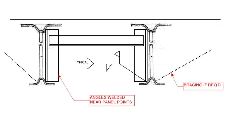
Something like this?
JOIST_DETAIL_rxdhff.jpg


Check out Eng-Tips Forum's Policies here:
faq731-376
 
dhengr and JAE,

Thanks for the input. I like the idea of cross member bearing/sitting in the crotch of the bottom panel point, then reinforcing the nearby top panel points (see sketch). We will have a talented welder on this project, but the curved shape of the formed top and bottom chord members makes it a challenge to add reinforcing angles.
 
 https://files.engineering.com/getfile.aspx?folder=08099fed-7130-4bd1-aa77-e19c67b38b1a&file=CCF_000024.pdf

- 250 lb is not that much of a load so I'm not overly concerned.

- Most of the joist in my area are this type. Frankly, I hate them for reasons just like this.

- With continuous webs like that, it raises the question of whether:

1) Web vertical shear is designed to exit one web, enter the chord, exit the chord, and enter the neighboring web OR;

2) Does the vertical shear simply stay in the webs, zipping around the radius somehow, and never enter the chords.

- If somebody with joist supplier side experience knows the answer to the above, I'd love to hear it. I think that it matters because, if it's #2, then the joists could, and indeed may, have been designed to only transfer horizontal shear into the chords at the weld. So yeah, I share your concern for any scheme delivering outwards, transverse load to the bottom chord.

- Two additional things lead me to wonder if the welds have only been designed for horizontal truss shear:

3) As you say, the welds tend to be small and:

4) I've tried to check the chord hat sections for web punching shear and that doesn't work well.

- I also love the crotch idea. I'd considered a legs up angle placed in the crotch and spanning from joist to joist if the geometry worked out. Top plate spanning the legs at the bolts.

OP said:
then reinforcing the nearby top panel points (see sketch).

I suspect that you don't need to do this precisely because of point #2 above. Hard to say for sure though so perhaps the additional caution is warranted. I'm assuming that you're only hanging load from the bottom chord panel points here.
 
KootK,

I like your term "chord hat section" to describe the formed chord top/bottom members. I'm reinforcing the adjacent top panel points to protect that tiny welds there. These joists will support a suspended grist case (grain handling equipment) at a brewery & taproom. Grain will be augered up into the container, so I think there is potential for some minor vibration that could work those welds loose.
 
TroyD said:
so I think there is potential for some minor vibration that could work those welds loose.

I do love to see an engineer's good judgment doing its thing.
 
I posted this somewhere else. Some bar joists are qualified by testing. No matter how funny the engineering looks, if they pass, they sell. Again, note that they also generally disregard some AWS requirements.
 
TroyD:
The reason I suggested some shaping/milling at the two lower edges of the “V” brg. blks. was to provide a better mechanical mating/bearing with the .75” round diags. even before welding. This starts to provide at least two lines or areas of bearing on each diag. and kinda locks the “V” blks. to the stl. jst. laterally, to some extent. This also has the benefit of moving the flare-bevel welds out to a position where they can/may be made with some degree of quality. They should also not be two short welds per side on each diag. That’s 8 starts and stops on what is a crappy weld in the best of conditions, I don’t care how good your welder is. Make those welds full length on each side, starting and stopping about .5” short of the edges of the “V” blks, and maybe unload the stl. jsts. (shore them, jack them up) when you do the welding. Finally, with a little more detailing on the “V” brg. blks. you could put spring or rubber bearing mounts btwn. your struct. framing and the top of the “V” brg. blks., if you are worried about vibration and fatigue.
 
TroyD said:
Grain will be augered up into the container, so I think there is potential for some minor vibration that could work those welds loose.

Actually, I've changed my mind on this. I really do think that you should avoid reinforcing the top chord joints. I think that it might actually be detrimental in addition to being unnecessary. Here's my sell:

1) As we've discussed, it may well be that all of the vertical shear is staying in the webs without ever entering the flanges.

2) That vertical load that you'd be designing for, if it does make it into the chords, will be present and vibrating at every joint all the way back to the joist supports, and with considerably more load coming in along the way. I doubt that you'd want to reinforce them all. Granted, I would expect any vibratory effects to attenuate some as it progressed through the webbing.

3) Even with a talented welder on board, it's damn hard to weld to the chords of the cold formed section without burn through. Part of why I try to avoid reinforcing joists of this morphology is because, more often than not, I actually wind up feeling as though the attempts at reinforcement have actually made the joists weaker instead of stronger.

4) As far as the vibration concern goes, that really translates into a fatigue concern at the webs. As far as I'm concerned, these reinforcement welding situations aren't ever clean and simple enough that I'd being willing to call them kosher for fatigue. Moreover, damage that is caused during reinforcing may actually make the existing stuff more fatigue prone than it would be otherwise.

If anything, I'd prefer to reinforce the top chord joints the same as the bottom, with those crotch plates. That way you're not messing with those delicate chords and you're doing welds that shouldn't be too bad for fatigue. Essentially, the strategy would be come one of doing your best to encourage vertical shear to stay in the webbing for a panel or two.
 
Status
Not open for further replies.

Part and Inventory Search

Sponsor