Continue to Site

Eng-Tips is the largest engineering community on the Internet

Intelligent Work Forums for Engineering Professionals

  • Congratulations KootK on being selected by the Eng-Tips community for having the most helpful posts in the forums last week. Way to Go!

Purlin with Bottom Flange Coped

Status
Not open for further replies.

T_Bat

Structural
Jan 9, 2017
213
Hey all,

I had an issue come up this week on a some modifications we made to an existing PEMB. Long story short, a new expansion was built adjacent to an existing PEMB. The new expansion has a higher roof. No one considered the new potential for snow drift on the existing roof so we were called to design some reinforcing for the existing. We ended up having them add a purlins intermittently to reduce the loads on the existing purlins. One area has been installed without issue. Now they are saying they can't roll the new purlins into place on top of the existing frames. They have already tried to lightly jack up the adjacent purlins and they still can't roll these over.

They want to notch (or cope) the bottom of the new Z purlins so they can install them. The contractor proposed they could use an angle or a plate welded down to the frame with the vertical leg bolted or screwed to the new purlins. I'm concerned about cutting the purlins - especially since this is the location of max shear and the potential web crippling issues (although that would be mitigated with bolting the new plates at the web). My approach would be to try to get the connection to the web out past the cope so little bending is applied on the cope. I've come up with (2) details but I'd love to get some feedback on issues I may be overlooking. [See attached details]

Option 1 is a plate welded down to the frame and bolted to the web. I've made the plate tall to help brace the end of the purlin for stability. I think this weld will be tough since the roof is still on the building.

Option 2 is an angle welded to the frame and screwed to the purlin web. I've extended the angle past the frame so it can be welded form the underside. The overhead weld is not ideal but probably easier than the down weld from above. My concern with this detail is that most of the purlin height is not engaged - feels like a stability issue.
 
 https://files.engineering.com/getfile.aspx?folder=6d3b1235-6346-4078-bef3-f4844bd1c546&file=Proposed_Purlin_Conn_Mod.pdf
Replies continue below

Recommended for you

Instead of an angle, I would use short pieces of rolled steel channel. Then you can use two bolts, centred over the frame, either vertically or horizontally.

Are the existing purlins bolted to the frame through the bottom flanges? Bolting through the purlin webs is much preferable.
 
Actually the existing purlins are attached with screws through the flanges. This occurs at the end wall "frames". The existing beams up here were replaced - the originals were (2) cold formed channels back to back and woefully overstressed by the snow drift.

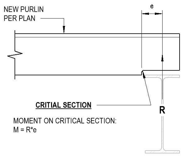
I thought about attaching over the frame - but then my critical section on the purlin will be at the newly "coped" section. I don't feel great about this... particularly when the cut may be jagged or have a sharp corner since it will be done in the field.
 
First, the connection between plate or angle and purlin is too far away from the supporting beam. As Hokie66 says, your connection should be centered over the beam. This would not be a nominal connection; it would need to be designed to take the full purlin reaction.

Second, it would be better to use an angle (or channel) to enable your weld to the beam to be parallel to the beam axis, not cutting across it. The weld shown seriously weakens the existing beam, particularly in difficult access areas. The weld between angle or channel to beam does not need to be designed to carry the purlin reaction as that member bears directly on the beam flange.

BA
 
Another approach would be to use a purlin that is not as deep. If your existing purlins are 200, use 150, heavier gauge purlins for the intermittent ones. Bolt them to a piece of channel which gives you the required depth. And as BA noted, with the load being only snow load, not uplift, the connection of the channel to the frame need only be nominal.
 
Thanks for the responses - you're right this is not a nominal connection, what I have shown is designed for the full purlin reaction. Here are my thoughts:

1. The beam we are welding to is new - it is erected but it can be shored for welding. It can be shored for welding, but this weld would occur ever 5 feet for the full length so it may be best to avoid the perpendicular weld across the flange for the reasons you (BA) point out.

2. The new purlins are already sitting on site. Ideally I need to use what we have instead of ordering 40+ new purlins.

3. I haven't thought about the channel idea - but it would be a similar approach to the angle. The benefit of the channel would be I could get a lighter channel that is tall enough to engage more of the purlin instead of the L3x3 I have shown. Again - I'm thinking of stability of the purlin here.

4. If we make the connection to the new purlin centered over the beam I'm not sure I trust the strength of the coped purlin section. The critical section will be on the corner cut from the bottom of the purlin. Since this will be cut in the field I'm not sure how certain we can be it will be adequately rounded to avoid some stress concentrations. Hence why I am trying to connect past the cut. Is this concern unwarranted?
Capture_xoqtuy.jpg


5. The supporting beams are continuous over some columns so I am already having them add bottom flange braces to the beams to brace the bottom flange. Seems like these could be used to resist the torsion induced on the beam. Alternatively, I could also design the bolts for the eccentricity assuming the reaction in on the beam centerline. You could argue this is just semantics, and that the structure will act how it wants to regardless of what I assume but this approach is taken all the time with steel connection design. (re: extended shear tabs).

Obviously I know you can't read my mind and some of the above info was not in my OP. Am I still way off here?
 
4. Your main connection should be centered over the beam; otherwise the purlin is supported eccentrically, relying on the angle or channel to cantilever out from the beam and putting a substantial torsion on the beam, not to mention unnecessary stress on the weld.

There is nothing wrong with adding keeper screws or bolts further out to provide lateral support to the purlin web. Just ensure that the main connection is adequate for the total purlin reaction.

BA
 
I think your concern about moment at that point is unfounded, but do your numbers yourself. But you are right to want to avoid a stress concentration there due to a sharp or irregular corner.

If you drill the corner, then remove the rest with a grinder, I think that should ease the concern about the corner. Warn the field crew about the sharp edges.
 
If the numbers and geometry supported it, you might header the new purlins off to their neighbors.
 
Back to the original problem of not being able to roll the purlins in. Why can't they just unscrew the roof sheets along that line over the beam?
 
KootK - I'm wary of heading off to the existing purlins due to web crippling issues. Admittedly I haven't calc'ed it but I'll take a look tomorrow. Hokie - that's a good idea. I'll propose that as another option before modifying all the purlins.
 
That would be the easiest, I think, if I am thinking your problem correctly. The only issue might be if there is flashing involved, but if it is all sheet metal, screws fix things, and silicone, of course. If you go that way, make sure they have a supply of the right type screws.
 
Status
Not open for further replies.

Part and Inventory Search

Sponsor