Continue to Site

Eng-Tips is the largest engineering community on the Internet

Intelligent Work Forums for Engineering Professionals

  • Congratulations KootK on being selected by the Eng-Tips community for having the most helpful posts in the forums last week. Way to Go!

SAP2000 frame deflection issue

Status
Not open for further replies.

jesussilvah

Civil/Environmental
Jan 18, 2019
7
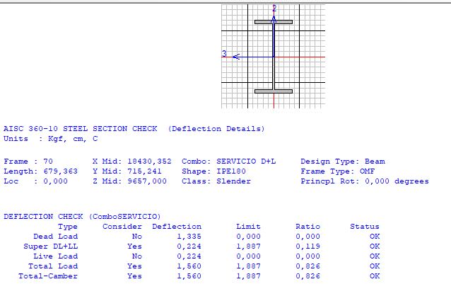
as far as i know there are two methods in sap2000 to see deflection on beams. Trough moment diagram 3-3 or in the design panel activating consider deflection in design.

the thing is both values differ from each other and dont know why.

wish someone can clarify this and tell me wich one is correct.

best regards.
1_iytbzg.jpg

2_ucw2v8.jpg
 
Replies continue below

Recommended for you

Different load case makeup perhaps between the pure analysis D+L and the design combos? Look into exactly what the design cases are calculating, for example if you have a composite beam there will be camber and shrinkage components for the design checks being accounted for.
 
Sorry I don't actually have sap2000, did you discount differences in load cases and design load cases due to the design cases consideration of other components?

I find in these situations that creating a smaller model to replicate & isolate the issue is a good approach, for example look at a single simply supported beam and examine the design reports, compare with hand analysis. Report back here the results of your checks as it may help others in the future.
 
when you refer to pure analysis D+L what do you mean? because i selected the same combination D+L as design combo so it shouldnt be any differences. also in this case its a complete steel structure with no shrinkage or composite elements.
 
Is there live load reduction being used in the design combo for example based on the design options you have chosen?

Create design combos that compare only constituent loads, i.e. isolate the gravity & isolate the live load into single cases, determine where the difference in deflection is occurring, is it in dead or live or both.

Which if any is correct based on a hand calculation, or using alternative software, you didn't say? Satisfy yourslef that the design output is relative to the beam ends as per the analysis window, etc.

Review the line loads in each case that tribute to the beams under display loads, perhaps one case is accounting for the self weight of the member and the other isn't.

Are there any errors in the analysis log?

You have not really explained what you have done to at least eliminate some possibilities?

CSI are usually quite helpful in taking a look, at the end of the day the discrepancy could simply be a program error. Their programs seem prone to them, especially in new versions (just check the change logs for example to see the varied bugs that get fixed, many which have been around for multiple versions of the program!).
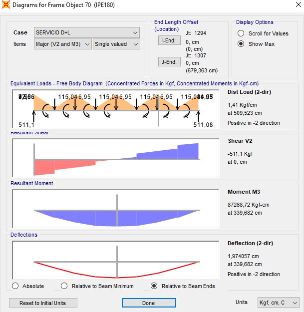
 
I notice you didn't include the end distances of the beam. the beam using normal beam calculation has no end distance but the I-beam below uses existing codes which might include the effective end distance. That means the I-beam calculated using the existing code is actually shorter than the beam above. Therefore, there is less deflection.

Also the beam above didn't says it is an I-beam. SAP2000 might consider it as a rectangular beam whether the I-beam below has more bending stiffness.

disclaimer: all calculations and comments must be checked by senior engineers before they are taken to be acceptable.
 
dear mronlinetutor

discounting the end distances of the beam it really doesnt make much difference of the values, for example. this beam is connected to a beam IPE200 and a IPE240 so i will have to discount from 6,8 meters to 6,58/360 = 1,83 vs 1,56 design value.

therefore i dont think this is the answer of this difference.

and the other possible explanation on the image above it says is an IPE180 beam, and its assigned to the frame element so the sofware should know is not a rectangular beam.

if you have other ideas i will be pleased

thanks for your time

 
dear agent666

i have played with the live load reduction factors on the design panel but there wasnt any major changes on the deflection result

i will follow your advice and isolate de loads because my idea is to determinate why the program behaves that way.

i know that the correct value is the higher comparing to hand calculations but i want to know why they differ.

checked the self weigth of the load case and its fine. theyre loaded with area elements that distribute to beams

there are not errors on the analysis log

thanks for your time and great advices

best regards
 
also ive tested in another model with a single supported beam with the same combination and the result are the same with no real difference so its extrange. will continue digging in to find whats wrong on the model.

with this result im discarding program error, beam end distances, live load factor reduction and variation of stiffness due differences of the beam section.
 
I have found in the past that using/relying on area elements to correctly distribute the load to beam elements often results in load being lost or incorrectly applied to the beams. This was in ETABs but the same might apply here, or they may have fixed it. It was especially true where you have one way spanning slabs that do not span orthogonal to the beam. The equivalent loading on your beam in the top picture seems to suggest this is occurring (can't tell because have no idea how the beam is arranged with respect to how its being loaded by the slabs). Also if using shells, because they have bending stiffness the load distributed to beam lines is affected by the continuity, so simple hand checks based on tributary width may not show the same loading and hence deflections.


As a test if you set the slabs self weight to zero and remove loads from the slab (or delete the slab and apply the correct line load to the beam itself, does it change the results for the design or analysis checks?

You can review what loads are being assumed to tribute to the beams from other elements like shells/membranes as one of the options under display loads.
 
did it, deleted the areas and charged the beam with a distributed load and the same ocurred, also isolated the load case to dead only and happened the same.

will continue testing

thanks for the quick response
 
One considers shear deformation (analysis) the other one doesn't, change shear stiffness on the beam to something high and see if results match.

Also for some of the design post processors such as composite beam, CSI uses Moment area method to calculate deflections, not results from analysis.

 
Status
Not open for further replies.

Part and Inventory Search

Sponsor