Continue to Site

Eng-Tips is the largest engineering community on the Internet

Intelligent Work Forums for Engineering Professionals

  • Congratulations waross on being selected by the Eng-Tips community for having the most helpful posts in the forums last week. Way to Go!

Deck Ledger at Brick Veneer

Status
Not open for further replies.

RFreund

Structural
Aug 14, 2010
1,878
Interesting new product from Simpson:

It has a lot of "caveats" in the notes, but it allows you to have a deck ledger on your brick veneer.
To be honest I really think bolting the ledger to the brick shouldn't be so frowned upon. The brick is masonry which we use for bearing all the time. The brick is tied back to the wall studs so it is braced laterally. You need to have some sort of lateral restraint for the deck that satisfies the intent of 2018 IRC Section R507.9.2 anyway. You might be woried about the eccentricity of the vertical load being applied to the brick, but won't the joist and decking restrain that rotation to some degree anyway?
I'd really like to see a deck that is bolted to the brick vs this connector. All other factors being the same.


EIT
 
The brick is masonry which we use for bearing all the time

yes, there is no problem in bearing.

The brick is tied back to the wall studs so it is braced laterally.

on modern brick builds that used seismic brick ties, yes. if they were done correctly. was it done correctly? what is the condition of the brick ties? the fasteners from the tie to the stud? do the ties hit the stud? when installing this new simpson ledger to brick, you are assuming the brick is A-OK.

You might be woried about the eccentricity of the vertical load being applied to the brick, but won't the joist and decking restrain that rotation to some degree anyway?

not especially, this is negligible.

the majority of modern day structural failures happen on decks. deck live loads are very dynamic. Decks get crowded, jumped on, danced on with all associated vibrations. its not hard to imagine how there could be outward load applied to the rim joist bolted to brick.

I would never mount a deck using this simpson ledge as a non redundant support to the floor system. I may consider using this simpson connector as a method to tie the construction together, if the deck has independant full structural support, taking into consideration the interactions between deck, brick and building, so that in a lateral event, brick won't come showering down on the people below.

 
I do not see the anchor using the brick for anything in their details. They have 2 tension screws and 1 compression strut in their system that pass thru the brick, not rely on it.

To actually use the brick as the support requires a lot of things to go right in the brick construction. Wall ties are just one example. Years ago I was a carpenter and we always had to nail the wall ties on while we were putting on the exterior sheathing (Gyp-board, plywood etc). I always felt it should be the brick masons job, not ours. My boss never let the brick mason do it. Only years later did I find out the "why". Brick masons tend to nail them on while laying the brick. While nailing on one, they are beating on a wall stud that just had a wall tie mortared into the joint just a few inches below. Beating on the stud loosened the brick tie below because the mortar was not set up. Even if it was set up, you can still loosen it by beating on the stud from the outside. So, I won't attach to brick veneers. Most brick veneers are laid with no inspection or supervision other than the mason themselves.

Also, decks can have an outward force to contend with. I doubt the deck will restrain rotation unless you provide some "rigidity" with screws etc.

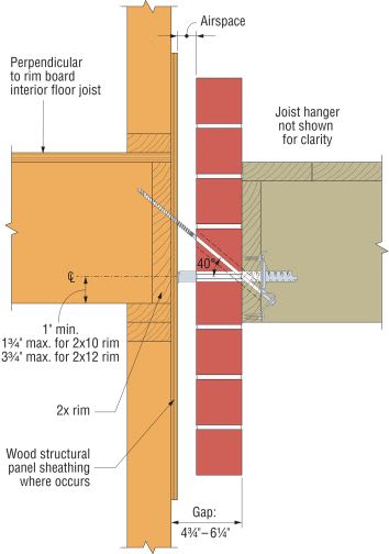
Note their statement: "The system enables the ledger to hang freely without bearing on the brick veneer." They are not connecting to the brick. They are connecting through the brick to the floor system of the main building. I do not think they are fastening to the wall studs. I like the fact their screws are angled upwards but wish their compression strut was angled also. Water down behind the deck will hit the compression strut and can "run to the wood" if it is level or sloped the wrong direction. If the screws were straight or angled wrong, the water would run to the wood, rot out the wood around the screw and then fail. Note in the detail I pulled from their site, the deck will attempt to make the rim board top rotate outwards and the bottom rotate inwards if the joist to rim joist connection were rigid. Rotating the top would reduce the effectiveniss of the compression strut.

Where I live, we have already had 3 different porches and decks pull loose from apartments that were not bolted through brick, they were bolted directly to the wood framing of the floor and had siding on the wall. Problem was water went down between the porch and the wood framing, ran along the "level" bolts to the wood, rotted around the bolts, pulled the bolt head and washer through the rotted 2x12 of the main floor. I fear the water as much as the brick veneer.

C_BVLZ_InstIll_Ill_Instld_SideView2x12_CY_fd9wf2.jpg
 
For you "load path" guys out there. At first glance I though the compression strut should have been below the tension screws rather than above it. When I did my load path, it looks correct.
[ul]
[li]deck boards span to floor joists[/li]
[li]floor joists span to rim joist[/li]
[li]rim joist tries to go downwards[/li]
[li]rim joist is fastened to Homer Simpson via 6 shear screws[/li]
[li]rim joist screws push down on Simpson and tries to rotate it counterclockwise[/li]
[li]tension screws hold Simpson up and are secured to main floor[/li]
[li]rotation of Simpson would be counterclockwise (not clockwise) since you are attaching on the left face (not right face)[/li]
[li]Compression strut is correct location provided it fastens to Simpson so that pushing on Simpson pushes on compression strut[/li]
[/ul]

Is that how you see this "contraption" working?
 
I was skeptical when I read the OP, but after clicking on the link and (quickly) reviewing the connector info on the Simpson website, I actually think it is a pretty elegant piece of hardware. Ron247 is right that it doesn't load or rely on the brick veneer at all. It has a tension tie (screw) and a compression strut. It says in the description that it attaches to "framing", but the instructions and illustrations clarify that it loads the rim joist. The notes below the allowable load table say that the designer is responsible for designing the rim board for applied moment, tension, and cross grain bending. This is annoying and it seems like for a standard installation, they could have checked this and included it in the allowable loads. As far as water damage goes, the notes say that the ledger has to be weatherproofed per code (flashing presumably). They also say you still need tension ties to the building.
 
It is advertised as intended for use on an existing structure, and providing ease of access for inspection. How is that inspection of the rim joist or other framing easy?
 
Regarding use of the brick as a supporting member (OP) the building code explicitly states that this is not allowed. I don't have the exact language of the code at hand but it is something to the effect of not supporting any load other than that of the veneer. I realize that many building authorities disregard this but .... just saying. A growing number of building authorities are recognizing this and enforce the code better.

As for the reasoning, I do not think that most brick veneer ties are capable of providing much resistance to buckling of the brick as a slender column, even if they are installed correctly (which I know from personal experience that they often are not). Most likely, a good quality seismic tie will have capacity in tension and compression but the minimum was ties are 22 gage corrugated which I think do not. In my area (Southwest Ohio) at one time not very long ago, most masonry supply houses only stocked 28 gage corrugated ties!

Consider the condition where there is a large opening below a wood deck (say a walk out basement condition) and the brick veneer extends to the lower level. With a deck having the ledger above and supported by the brick, I would say that there could be a substantial load on the brick "columns" at each edge of the opening. I realize that additional veneer ties are supposed to be installed there normally but... as I wrote earlier, they often are not.
Even if one could rationalize the loads, the explicit language of the code may be difficult to go against.

Looks like a clever piece of hardware but I don't think it is very redundant and the learning curve may be steep. I agree that the "inspection" portion seems a bit weak.
 
Seems like a nifty little piece of hardware. I like the load path as it does not seem to rely on the brick. Wonder if they will be available for DIY'ers in those big box stores.
 
Houseboy said:
As for the reasoning, I do not think that most brick veneer ties are capable of providing much resistance to buckling of the brick as a slender column

Houseboy,

I agree in principal but my field experience says otherwise. We have tons of veneer houses around here with 10-20 ft. of brick above a garage with two 9 ft. doors separated by a 12" brick column. I have yet to see any type of distress or failure. Probably, the brick is acting as a deep beam and distributing the load to other areas.
 
Sorry my OP was a little confusing.
I do think that this is a creative connector. But, In general, I just think though bolts that extend through the rim joist, through the brick and through the ledger would do the same job. I'm not saying I would sign off on it and fully agree on the theoretical arguments against it, but I'd be curious to see both systems tested to failure, which would go first.


EIT
 
Through bolts thru the brick will automatically place vertical loading on the brick.
This produce avoids that issue by placing no vertical load on the brick.
 
Thru-bolts through the brick without some sort of compression strut also allow horizontal/lateral load to be applied against the face of the brick. I've never been comfortable with this. It could be a problem just from tightening (over-tightening) the thru-bolts.
 
Through bolts would be shear and bending on the bolts due to the moment arm. Bolt bearing on the brick is the only support the brick can possibly contribute to alleviate those forces. The bolt would have to be grouted in the hole in the brick. What is the allowed brick strength for a concentrated steel load on brick? If you crack the brick, you loose your reduction in moment arm.

XR250: I too, rarely see problems with double 9' garage openings. I do see a lot of cracked brick on 16' to 18' garage openings. Many residential jobs here do not attach the steel shelf angle to the wood header that spans the opening. They do not use that huge angle option the code shows for wide openings either. I think it is two L6x6 angles. The use a L4x5 etc for the entire span. Most brick angles can span 5' to 7' with no real problem. For that reason, the 9' opening is not that far out of bounds, but the large openings are.
 
I am intrigued, but a little confused by the design.

I follow and agree with Ron's load path. The rim joist is assumed to rotate COUNTER-clockwise, which gets the strut into compression.

I could be wrong, but I thought many deck failures started at the opposite free side of the deck. Something happens with a post or joist connection to a post causing a localized failure. Then loads shift dramatically causing the major failure back at the ledger. Often this results in the entire ledger pulling away from the structure or the joists get ripped out of their joist hangers at the ledger board.

What would happen to this connector if everything gets thrown into tension as a deck tries to pull away. The strut ceases to be a strut and becomes a tension member too. I wonder if it still works?
 
JoelTXCive, I don't think the connector would work if subjected to pure tension away from the wall. For that reason, you still have to have separate tension ties between the deck and the building per the code. The Simpson notes mention this.
 
My confusion is in how you guys are seeing the rim rotating counter-clockwise!!

The 3/8" x 14" long screw is pulling outward and downward (at a 40* angle from horizontal) on the upper half of the rim.
The 31/32" diam strut is pushing the bottom half of the rim inward.

I would call that clockwise rotation of the rim. Maybe I'm missing something. Help me out?
 
I don't see how this connection imposes any real loads on the brick. To me, its like a mini truss: screw is in tension, horizontal strut in compression, vertical load due to the ledger.

Draw the force triangle.

The rim board can't rotate because (supposedly) it has joists every 12" to 16" or so.
 
It imposes zero loads on the brick. That is the whole point of the connector.

I don't follow all of this discussion about things rotating clockwise or counterclockwise. Maybe there is some confusion in this thread about use of the terms rim board and ledger board.
 
A lot of houses around here have I-joists for bands or a 2x4 truss ribbon. Hopefully no one will use it in those situations.
Also, as Houseboy suggested, the rim can rotate if the house joists run parallel to the band.
Simpson is real good at selling products like this that contain way too many caveats.
 
The connector does not appear to be good for direct tension. The deck failures that occur on the opposite side away from the brick tend to be soil related such as post erosion near a steep embankment or really tall decks without proper lateral bracing.

My thoughts are it rotates CCW where you generally think of this type of connection rotating CW. The difference I think (but I could be wrong) is that the Rim Board (the lumber against the brick) is routing the load to the Simpson, but it passes the load to the Simpson through the 6 screws and the load path is through the left side of the bracket, not the right side. I know when I originally looked at the bracket, I felt the Compression strut was in the wrong location because I was thinking CW rotation. My mind had to correct that before I could fully appreciate how the bracket works.

Visualize the bracket as being thicker, the downward rim joist load is attached on the left side of the bracket and is off-center of the bracket. Thus, it attempts to rotate the bracket CCW.

 
Status
Not open for further replies.

Part and Inventory Search

Sponsor