Navigation
Install the app
How to install the app on iOS
Follow along with the video below to see how to install our site as a web app on your home screen.
Note: This feature may not be available in some browsers.
More options
Style variation
-
Congratulations TugboatEng on being selected by the Eng-Tips community for having the most helpful posts in the forums last week. Way to Go!
You are using an out of date browser. It may not display this or other websites correctly.
You should upgrade or use an alternative browser.
You should upgrade or use an alternative browser.
Difference between datum of a Cylinder surface vs Cylinder Axis.
- Thread starter R1chJC
- Start date
- Status
- Not open for further replies.
- Thread starter
- #3
R1chJC,
I would say your figure on the right is probably bad practice. See Y14.5-2009 Fig 3-4 for some different accepted placements of datum feature symbols on features of size. If the feature's diameter is specified with a +/- tolerance, although attached to the feature differently (a), (b), (c), (e), and (g) all *derive a datum axis from the datum feature in the same way.
*Edited for clarity
The figure on the right is not bad practice, but one that communicates a different intent than the figure on the left.
Figure on the left: the datum is the center plane of the width feature of size.
Figure on the right: the datum is the tangent planeif of the top surface.
Figure on the left: the datum is the center plane of the width feature of size.
Figure on the right: the datum is the tangent plane
Noted that the diameter symbol is missing from the figure shown so it would be width shaped. OP's question was initially about cylindrical features. Perhaps they can clarify whether they meant to change their question from a cylindrical FOS to a width FOS.
- Thread starter
- #9
R1chJC,
Thats what I figured - my mind was stuck on cylinders and didn't even notice it was missing until Sem's comment.
I stand by my initial comment then with the clarification that the one on the right if meant to refer to the entire surface of the cylinder is at best misleading/improper and if meant to refer to a plane tangent to the cylinder surface is invalid.
ASME Y14.5-2009 para 3.3.2:
"(c) placed on the outline of a cylindrical feature surface or an extension line of the feature outline, separated from the size dimension, when the datum is an axis. For digital data files, the triangle may be tangent to the feature. See Fig. 3-4, illustrations (e) and (g)."
It has to be noted though that illustration (e) and (g) only show the datum feature symbol placed on the outline in a view where it is shown circular. But, it still seems like the figure on the right posted above conforms to the standard.
Sem,
By the letter of the standard, I can see how you would say thats allowable. I would not personally utilize that notation as I find it misleading and considering there are no examples of such in the standard would not recommend others to do so. I can't see where that would be preferable to literally any of the other shown methods.
Regardless - discussion of proper notation notwithstanding, OP's question was in reference to how the datum feature/axis would be defined. Even if it were allowable, it would not change the second part of my initial comment that "although attached to the feature differently [...][they] all derive a datum axis from the datum feature in the same way."
chez311,
I agree. Although thequestion answer to R1chJC's question : "Are the two call-outs below legal in ASME then?" Is probably yes, I can see how your alert regarding the right side option has its' place.The answer to the second half of the question "so how do they differ?" Is that from the standpoint of geometrical meaning - they don't.
I agree. Although the
Folks,
Does anybody out there have an authoritative statement that defines the GD&T default conditions that create a simultaneous requirement (one functional group) from a set of features controlled with position and/or profile tolerances?
ElectroMechanical Product Development
(Electronics Packaging)
UMD 1984
UCF 1993

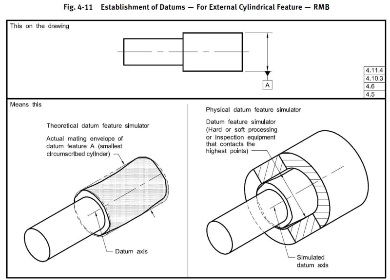
This defines the axis of the cylinder as the reference.
Placing the Datum on the surface of the cylinder instead on the diameter dimension would define the cylinder surface as the reference which really doesn't make much sense.
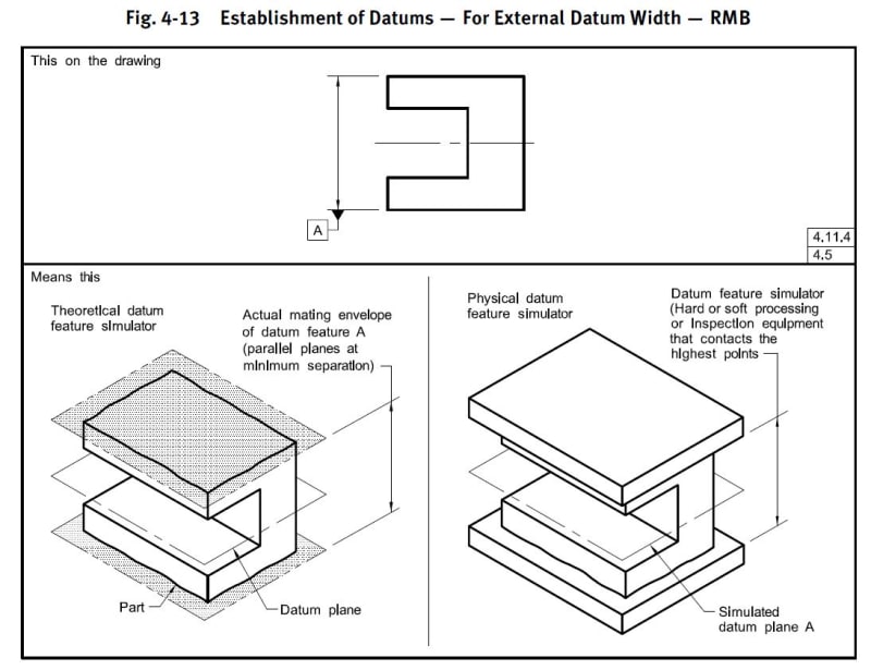
This image would be of a flat or rectangular part where it actually makes a difference

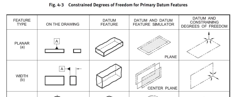
In the left image, Datum A defines the center plane between the two surfaces as the reference plane.
In the right image, Datum A defines the surface it is attached to as the reference plane.


- Status
- Not open for further replies.
Similar threads
- Question
- Replies
- 25
- Views
- 25K
- Locked
- Question
- Replies
- 3
- Views
- 2K
- Locked
- Question
- Replies
- 9
- Views
- 3K
- Locked
- Question
- Replies
- 14
- Views
- 6K
- Replies
- 21
- Views
- 22K

