Eng-Tips is the largest engineering community on the Internet

Intelligent Work Forums for Engineering Professionals

Seismic Design of Cantilever Stringer Staircase

Status
Not open for further replies.

fracture_point

Structural
Mar 7, 2019
58
0
0
CA
Hi all,

Hoping you can offer me some guidance/point me in the right direction with resources to my current problem.

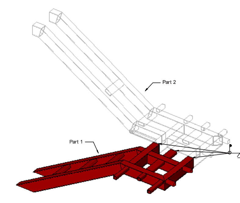
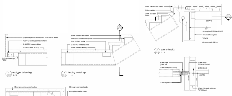
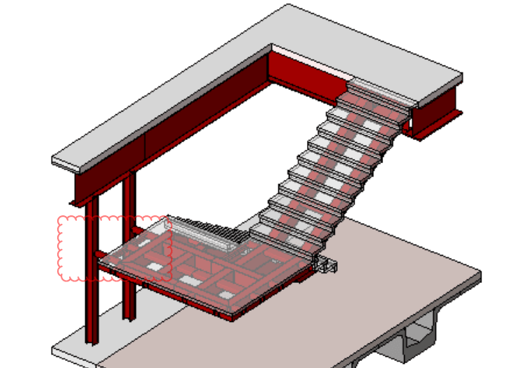
The architect wants a staircase that is cantilevered from the main structure suspended into an atrium space (see attached paint diagram). It is likely these moment connections will have to come from embedding the stringers some distance into the floor slab to provide full rotational restraint (moment capacity).

This is a high seismic zone and the structure is very stiff and therefore falls within the peak response of accelerations. I have a couple of concerns:

1) Vibration of the floors. I believe I can find plenty of guidance on this in published work.

2) The stairs are rigidly connected to the structure. Therefore, when the structure moves the stairs will too and this will induce seismic forces in the stairs. There is not any redundancy in this system, so in my eyes it is critical for this structure not to develop plasticity at the moment connection as this will cause instability due to no restraint against rotation. I cannot find any resources on determining the seismic load to design this system of stairs for.

Is it necessary to complete a modal analysis of the stairs also? I suspect that the stairs have some flexible modes in the Z-axis due to their cantilevered nature.

Thanks in advance.
 
 https://files.engineering.com/getfile.aspx?folder=719780b8-760f-4837-9620-6e0f11de7226&file=cantilever_stairs.PNG
Replies continue below

Recommended for you

I don't really consider this my wheelhouse but, since nobody else has replied, I shall do my best.

fp said:
It is likely these moment connections will have to come from embedding the stringers some distance into the floor slab to provide full rotational restraint (moment capacity).

Firstly, I don't feel that these connection necessarily do need to be moment connections. Usually, these types of stairs work by the formation of a simple, two member truss of sorts.

Secondly, were there to be a moment connection, I think that your best bet would be to install embed plates with deformed bar anchors at the slab edges and weld your stringers to those. Embedding your steel seems messy and not very tolerance friendly in my opinion.

fp said:
There is not any redundancy in this system, so in my eyes it is critical for this structure not to develop plasticity at the moment connection as this will cause instability due to no restraint against rotation.

I disagree but my disagreement is really a function of the model that I described above. I'd make the thing stable by way of the two member truss and intentionally allow one or both of the connections to yield or rotate freely, thus allowing them to accommodate the expected building drift. One of the consequences of using the two member truss concept is that you won't be able to provide a horizontal slip joint at the floor levels. Doing so would great a flexural demand in the stringers that would be onerous and very prone to vibration issues.

fp said:
I cannot find any resources on determining the seismic load to design this system of stairs for.

I think that a prudent approach to demand would be to design for drift compatibility as we do with gravity only columns in flat plate, concrete structures.

fp said:
Is it necessary to complete a modal analysis of the stairs also? I suspect that the stairs have some flexible modes in the Z-axis due to their cantilevered nature.

I'm not clear on what you're asking here. Are you referring to:

1) Modal analysis of the primary building seismic system including the effect of the stairs OR;

2) Modal analysis of the stairs themselves for vibration? I would think that you'd wind up doing this as part of your vibration analysis anyhow if, in fact you're doing one.

c01_jimxya.jpg
 
KootK - This is very coincidental because I spent some more time thinking about the problem recently since I hadn't had any comments and come to pretty much the exact conclusions as you.

If the main stringers are tied together rigidly with cross members at the landing level, they do certainly behave with truss action.

My design solution is as follows:

Part 1: Model the solution of the stairs rigidly fixed to the slab to develop some fixed moment and ensure that my embedded reinforcement connection can develop enough not to cause any type of pull-out failure. Although primarily the structure does want to behave with truss-like action, having fixed connections do increase some of the load resisted in bending.

Part 2: Model the solution pinned to the structure. This represents plastic hinges forming and allowing rotation, and ensure that the structure will remain stable due to increased truss-like behavior (and therefore increase in axial loads) without failure.

Part 3: Model the stairs in an independently to the rest of the structure to determine modes and frequencies and sub-sequential vulnerability to vibration from ascending and descending the stairs.

Extending a couple more question to you: What do you mean by drift compatibility? Is this akin to including the stairs within my global ETABS model to determine the deflection at the point which the stringers connect to the main structure, which will impose forces into the stairs themselves?

And I'm hesitant to specify a complete weld to the embedded plate as I know in the past these types of connections can experience a brittle failure. Do you think this would be of concern and I should use some type of bolted connection?

Cheers!
 
fp said:
What do you mean by drift compatibility?

Similar to what you described. Figure out the inter-story drift if the stair were not present and then ensure that the stair connections could survive the loads / deformation implied by that inter-story drift.

fp said:
Do you think this would be of concern and I should use some type of bolted connection?

No, I don't. I don't see this as a super critical moment connection given that it's not part of the primary lateral system. Additionally, you should be able to design the connection to encourage failure to be by yielding of the deformed bar anchors behind the plate rather than failure of the welds. Kind of version of a poor man's capacity design.

The stair connection is a bit important in that it's part of emergency egress but, really, all that it has to do under seismic is not fall off. If you fracture the flange welds and are left with a few inches of web weld, you're probably still in good shape.

 
I think you guys are on the right track. One thing to be careful of is your perfect truss model usually has the up and down stringers offset. This creates a lot of twisting to deal with the eccentricities. So make sure you explicitly model this effect.

This one below was designed all fully welded with continuity members going back into the landing. Ensure you model everything to capture the twisting effect and as Kootk noted imposing the drift on the stairs is pretty critic step. For a stair you might consider imposing not just the ultimate limit state drift but instead the maximum credible earthquake as if there's a stair failure its a critical part of the egress system.
MIT_OpenDay_20140801b_f8wptq.jpg
 
Agent666 said:
One thing to be careful of is your perfect truss model usually has the up and down stringers offset. This creates a lot of twisting to deal with the eccentricities

It certainly should be considered in the design but, for the sake of deformation compatibility, I actually think this is an asset. The added internal flexibility means less force generation for the same inter-story drift. The thing can just twist all cockeyed at the landing and life carries on.

 
I guess, the eccentricity creates a lot of secondary actions such as moments, torsion etc that needs to be explicitly considered and not ignored is my point.

I take back what I said about there being continuity members back into the floor, I found the detail and refreshed my memory, it was pinned top and bottom a big arse pin with a continuous structure consisting of both flights with lots of interlinking members. They ended up with a pretty substantial box section made out of 300 channels, and some lighter members on outriggers out to the edge to give it a lighter architectural look.
See below:-
Capture_pd3b9u.png

Capture_tibdbg.png


Edit:-

One other thing, at midheight landing they had ties back to some columns to deal with the seismic load/drift orthogonal to the flights, don't forget about the load in this direction:-
Capture_idc4pf.png
 
Agent666 said:
One thing to be careful of is your perfect truss model usually has the up and down stringers offset. This creates a lot of twisting to deal with the eccentricities. So make sure you explicitly model this effect.

Yes, I've actually included the stringers and slab in the global ETABS model and it definitely captures the twisting motion due to the 'imperfect' truss action.

KootK said:
Similar to what you described. Figure out the inter-story drift if the stair were not present and then ensure that the stair connections could survive the loads / deformation implied by that inter-story drift.

Is this necessary to do if I've actually included the stairs into the model? I've tied the stringers into the nodes on the slab so that there will be deformation compatibility between them. Then the finite element analysis should calculate the imposed forces to create these deformations.
 
As shown in Agent's latest, I'd considered a true hing for the connection. The viability of that will depend heavily on aesthetic requirements?

fp said:
Is this necessary to do if I've actually included the stairs into the model?

Nothing is "necessary" in this space. You're very much in the real of engineering judgment in this space. That said, I personally would not be including the stairs in your global, lateral load model. In my opinion, there's just too much uncertainty inhering in the stair behavior to be allowing that to be impacting the design of your primary lateral system. As such, I'd do one of these things:

1) Do not include the stair in your global, lateral model and design it for deformation compatibility as discussed OR;

2) Do both #1 and include the stair in the model and envelope those results.

I'm not a fan of what I would consider to be overly complex, global modelling. Structural engineering isn't about "knowing" anything. Rather, it's about roughly, and hopefully intelligently, approximating everything.
 
I believe while you have it modelled, your model won't pickup the peak interstorey drifts. Non-linear time histories have shown the peak drift can be of the order of 50% higher due to higher mode effects. This is due to a model analysis effectively averaging out some of the modes and being first mode dominant.

Not sure how your code deals with this, but often when assessing your drift limits there is an additional scaling factor based on building height that needs to be adding in before comparing to your say 2.5% drift limit. Any secondary components need to be designed for the peak drift and the compatibility actions resulting from this. In NZ we are required after the Christchurch earthquake sequence in 2011 to design for 1.5/0.7 * the design drift for elements critical to the egress such as stairs/ramps, etc. Same applies for critical transfer structures under seismic loading.

We had quite a few stairs that failed in these events, resulting in people becoming trapped in high rise buildings with no means of escape.

The Royal Commission recommendation was to approach this on the basis of requiring you to design for these elements to have sufficient clearance to accommodate the mother of all earthquakes (design event scaled up to MCE event (maximum credible earthquake)).

This has now filtered down into our standards (about 5-6 years after the event). It stands to reason if you are (rigidly/semi-rigidly) connecting two levels via secondary structure in a way that they are going to be subject to compatibility forces to reach that level of drift, then these secondary elements need to be designed for the same event and the compatibility forces that result if they are required to remain serviceable after the event.

Earthquakes can be significantly larger than the value you typically design for, in recent earthquakes here in NZ parts of the spectrum have been double the design spectrum acceleration. It's important to remember the design earthquake is simply a probabilistic approach to minimise risk and economics of building to an acceptable level. As such some earthquakes will enviably be stronger than the design level event.

I believe you also need to make sure your stairs aren't bracing the building, so comparison with response without the stairs in your model is probably a good thing to undertake. If found to significantly alter the response I'd be looking at ways of isolating this so it did not occur.
 
To open up this wormhole slightly again...

I modeled the stairs independently in SAP2000, and applied a deflection of 0.01h (drift limitation by code) at the pinned connections of the stairs. Obviously though, the forces induced by into the system by this deflection depend on the stiffness of the members. The more stiff the members, the more force applied to the system to move the supports by 0.01h.

I feel like that applying the force as a displacement of 0.01h isn't given me accurate representation of the forces that will develop, as for a W360 member the forces are very small! (in the magnitude of 10knm minor bending moment).
 
Post a screenshot of your model/arrangement to see if everyone agrees with the arrangement, if you've created an arrangement that pivots, rather than resisting the movement you'd expect the induced loads to be relatively low.
 
Agent666 said:
Post a screenshot of your model/arrangement to see if everyone agrees with the arrangement, if you've created an arrangement that pivots, rather than resisting the movement you'd expect the induced loads to be relatively low.

Attached some images. The lateral movement is resisted by minor axis bending of the stringers. I reduced the stiffness of the area element to zero in the direction of the lateral (global Y) displacement.

If I increase the section size to something larger I gain more moment, as expected as a large section requires more force applied to the member to move it 45mm. However, I'm not sure that the way I'm modelling this accurately represents what is happening with the deformation compatibility between my stairs and structure. I feel that regardless of the member stiffness that I am using, the same forces should develop within the stairs when the main structure moves 45mm.
 
 https://files.engineering.com/getfile.aspx?folder=65a3582e-58ca-4139-8844-0df79c9227f6&file=eng-tips_stairs.pdf
What is the shell in reality? As you note stiffness is important, simply ignoring it, or counting it from the treads is quite important. If you were truly ignoring it you also need to reduce the shear stiffness?

If I was doing this, I'd look to isolate each tread to minimise the load going through these, i.e. they could be individual precast treads bolted onto the stringers or similar and not contribute to the resistance.

I'd then model it as just the stringers with applied loads vertical loads and imposed drifts.

Don't forget you also have to consider the drift in both directions, and possibly some in between vectors. The other direction it is a lot stiffer in my view and you'll end up with bending/axial/shear to consider in the stringers and intermediate landing.
 
In my opinion, you're on the wrong track here with the complex modelling of the staircase. These systems are highly indeterminate, complex, and riddled with things that may impact stiffness substantially including, but not limited to:

1) Hand rails
2) Kick plates
3) Treads and risers not being flat plates
4) Contributions of finishes

I think that you need to look at something like this before modelling and ask yourself if I do this, will my confidence in the results really justify the effort?. For me, the answer would be no and I would instead take this approach:

5) Model the stair as a two, rigid truss members as I suggested earlier. This can be a pen and paper exercise.
6) Impose the interstory drift.
7) Assume all drift is accommodated at the stringer to slab connections.
8) Design stringer to slab connections so that they are ductile and won't fall apart under the imposed drift.
9) Move on.

Frankly, I wouldn't even bother trying to design the stairs themselves for the imposed drifts. Because these systems are highly redundant, naturally well braced, and usually governed by serviceability, the odds of a catastrophic failure happening anywhere other than at the slab connections is pretty much nil.

No matter what we tell reviewers and EIT's, there isn't a structure out in the wild anywhere that's designed for everything. Engineering judgment always enters into the choice of what ought to be checked, even if it factors in nowhere else. So let it be your friend here.

 
Agent666 said:
What is the shell in reality? As you note stiffness is important, simply ignoring it, or counting it from the treads is quite important. If you were truly ignoring it you also need to reduce the shear stiffness?

I was actually doing two things. For design of the stringers, I will modelling the shell element without stiffness contributing to the resistance of the global Y direction drift. This was to be conservative in the design of the stringers themselves. I was utilizing the stiffness of the shell (i.e. not reduced) in the modal analysis to determine susceptibility to walking vibrations and was intending to detail the steps to provide the diaphragm rigidity I am relying on in my model.

Agent666 said:
I'd then model it as just the stringers with applied loads vertical loads and imposed drifts.

Sure, I can definitely follow this method as it seems like a nice way to approach it. However, I still have confusion regarding my question from my previous post about the stiffness of the stringers affecting the force developed in the stringers. If we talk about the y-direction case only (for now, I will consider x-direction and any combination of these I think may be critical), imposing the 45mm deflection will develop less force in the members if they are more flexible and more force if they are stiffer. However, following that logic, if I use small sections I develop extremely low forces in the members when moving the reaction 45mm. If there a better way to approach this?

KootK said:
I think that you need to look at something like this before modelling and ask yourself if I do this, will my confidence in the results really justify the effort?. For me, the answer would be no and I would instead take this approach:

5) Model the stair as a two, rigid truss members as I suggested earlier. This can be a pen and paper exercise.
6) Impose the interstory drift.

KootK - I can definitely do this, but my question above to Agent666 still remains. If I model it as a 2D > shape truss, and impose a 45mm displacement at the top connection, the amount of force out of plane (bending) developed in the stringer will depend on the stiffness of the member i.e. it requires less force to move a flexible member. So by that logic, if I assign a small member, the forces are pretty much negligible?
 

More detail:

1) Design the stair ignoring seismic and settle on your member sizes.
2) Model the stair as a two, rigid truss members as I suggested earlier. Pins at both slab and stringer connections. Nothing fixed, no stiffness dependency for this step.
3) Assume all drift is accommodated at the stringer to slab connections.
4) Impose the inter-story drift and record the relative angular change between the slab and the stringers.
5) Use the rotation from #4 applied to the end of the stringer as sized in #1 to generate a moment at the slab connection assume the other end of the stinger is fixed for conservatism. 4EI/L etc.
6) Design stringer to slab connections so that they are ductile and won't fall apart under the moment from #5.
7) Move on.


Of course if the member is stiffer it takes a larger force to push it the same distance, think about say designing a normal member, you make it stiffer to make it deflect less under the same loads. Here the you are talking about a constant deflection, so if it's stiffer you need to apply a larger force to get the same deflection. Larger force = larger design actions.
 
KootK said:
More detail:

1) Design the stair ignoring seismic and settle on your member sizes.
2) Model the stair as a two, rigid truss members as I suggested earlier. Pins at both slab and stringer connections. Nothing fixed, no stiffness dependency for this step.
3) Assume all drift is accommodated at the stringer to slab connections.
4) Impose the inter-story drift and record the relative angular change between the slab and the stringers.
5) Use the rotation from #4 applied to the end of the stringer as sized in #1 to generate a moment at the slab connection assume the other end of the stinger is fixed for conservatism. 4EI/L etc.
6) Design stringer to slab connections so that they are ductile and won't fall apart under the moment from #5.
7) Move on.

Please forgive my ignorance KootK, still having trouble determining exactly your method. I've attached an image of my understanding of it.

From the image, you could back-calculate the moment required to give this rotation and then design the member for that?
 
 https://files.engineering.com/getfile.aspx?folder=a49697d2-5068-49cd-a59f-fb02926211ab&file=KootK_method.PNG
I see where we've gone off the rails now. I was thinking of movement parallel to the stingers where your concern seems to be movement perpendicular to them.

 
Status
Not open for further replies.
Back
Top