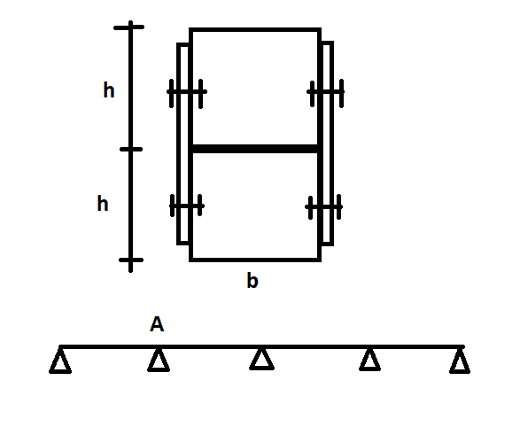
Apologies if in my brief search I missed threads which would clarify my below question. For the calculation of some wooden members, I was recently confronted with the problem mentioned in this post. I note that since then the matter was fully resolved in another way (unrelated to this post), so this post basically represents an itching curiosity of mine.
Consider a multiple span beam as shown in the attached sketch. The beam is built up from two identical members on top of each other, c.s. dimenions b x h. The intention is to fasten them together on their sides, so I am interested in this specific problem and not, for example, if there is a better structural solution to achieve composite action for the members. The question is how to calculate the spacing in the longitudinal direction of the beam between fasteners.
My understanding is that the correct approach would go something like this:
Vmax (at point A) = line load * l * 0.571 (l is spacing between supports)
Q = b*h*h/2 (first moment of area of the top beam)
I = b*(2*h)^3/12 (second moment of area of the full cross-section)
q = Vmax*Q/I (shear flow)
s = 0.5*q/Frd (s - spacing between fasteners, Frd - shear resistance of fastener (including bearing and all other similar criteria)
I then further understand that if needed, instead of Vmax I can use V(l) and vary the spacing between fasteners acc. to how the shear force along the beam varies. The issues I would like to address are:
1. Would you consider the above approach correct? When doing these calculations, with real values, the resulting maximum spacing was much, much lower than I would have expected.
2. I am uncertain of the implications due to the fact that the interface between the two beams and the location of horizontal shear force transfer at fastener locations are not the same. Does anything 'funky' happen with the lower half of the top beam / upper half of the bottom beam? Are they 'engaged' in the current configuration? Any necessary modifications to the expressions above due to this? Does it matter where where the fasteners are located (e.g. if the fasteners for the top beam would be at h/4 from its base compared to h/2 in the sketch)? If so, what is missing / wrong in the expressions above?
Any thoughts are much appreciated.

