Hi,
I am new to this forum and I am a graduate.
I have been asked to calculate the footing reinforcement for a 15 m high light pole. The footing is to be 700 mm in diameter and is to be reinforced. The footing is to be poured in situ in the ground.
To do this I made a model of the light pole in Space Gass and inputted my loads wind loads etc to help me generate the design ULS loading. I got the worst case loading as follow:
N*= 6kN M*=120kNm V*= 15kN
These are the loads that the top of the pile footing will experience due to the loading from the light pole.
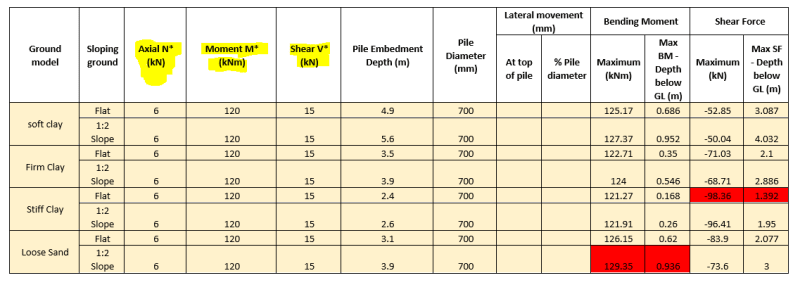
The light pole footing is going to be constructed in several different soil types. So I sent the above loads to our geotech engineer. He carried out some analysis for different ground models and essentially came back to me with the following table:

In his model he tells me to use the highlighted red bending moment and shear force values for designing the reo. We intend to use the same steel reo design for all the pile footings. In another table he also gave me all the pile lengths for different soil conditions.
What I intend to do is:
1) Use the BM he provided and the axial load I calculated above and plot these on my interaction diagram to see if my reinforced concrete pile can handle these loads.
But here is my question:
What do I do with the shear force load he has given me? I am kind of lost. Is it for me to do design the Shear ligatures? I have no idea how to design shear reinforcement for the pile. Could someone please shed some light?
Any help is much appreciated.
Regards
I am new to this forum and I am a graduate.
I have been asked to calculate the footing reinforcement for a 15 m high light pole. The footing is to be 700 mm in diameter and is to be reinforced. The footing is to be poured in situ in the ground.
To do this I made a model of the light pole in Space Gass and inputted my loads wind loads etc to help me generate the design ULS loading. I got the worst case loading as follow:
N*= 6kN M*=120kNm V*= 15kN
These are the loads that the top of the pile footing will experience due to the loading from the light pole.
The light pole footing is going to be constructed in several different soil types. So I sent the above loads to our geotech engineer. He carried out some analysis for different ground models and essentially came back to me with the following table:

In his model he tells me to use the highlighted red bending moment and shear force values for designing the reo. We intend to use the same steel reo design for all the pile footings. In another table he also gave me all the pile lengths for different soil conditions.
What I intend to do is:
1) Use the BM he provided and the axial load I calculated above and plot these on my interaction diagram to see if my reinforced concrete pile can handle these loads.
But here is my question:
What do I do with the shear force load he has given me? I am kind of lost. Is it for me to do design the Shear ligatures? I have no idea how to design shear reinforcement for the pile. Could someone please shed some light?
Any help is much appreciated.
Regards
