Continue to Site

Eng-Tips is the largest engineering community on the Internet

Intelligent Work Forums for Engineering Professionals

  • Congratulations KootK on being selected by the Eng-Tips community for having the most helpful posts in the forums last week. Way to Go!

Thrust Analysis 2

Status
Not open for further replies.

Bowsers

Structural
Nov 19, 2019
35
I am doing a solar panel on roof design. I have been asked by the plan checker to show the analysis of the thrust on this system. I must admit I’m not exactly sure what “thrust” is in this context. Is this additional outward force applied to the walls by an increase in load on the roof?

This particular residence has two roof shapes,
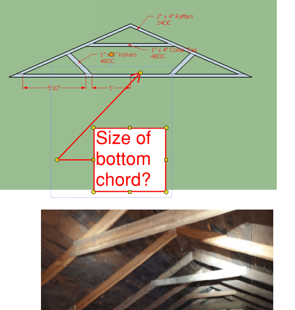
1) Typical roof, with rafters, rafter tie, collar tie
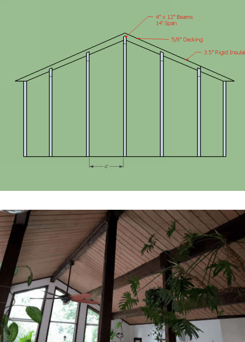
2) Vaulted ceiling with rafters, beams and intermediate columns supporting beams.


In condition 1, there would be no thrust as the load is being handled by the tension capacity of the collar tie.
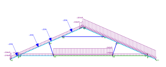
image_rhtxts.png

Pinned left side, roller right side.

I would go under the assumption there is no additional thrust in condition 2, because all the load is being directed downward through the intermediate columns.
image_msyjz5.png

Pinned left side, all other reactions are rollers

Based on what I’m seeing, there isn’t a reaction in thrust, unless make both ends of each rafter pinned. Is that the right way to determine loading? Thank you.
 
Replies continue below

Recommended for you

I don't see a collar tie in condition 2. I see a collar tie and rafter tie both in condition 1.

Is the ridge beam in condition 2 designed for flexure? I believe that is what has been described.
 
The previous post has been updated.

Are you asking about the resulting thrust at the end of the bearing beams at condition 2? I had not considered that.

Condition 1
image_zmewk0.png


Condition 2
image_usf8e0.png
 
Condition 2 does not have thrust. Thrust is generated outward due to sagging ridges.
 
If you want to know the thrust load, both of your support points should be pinned and the horizontal reaction equals the thrust load. By putting a roller on one end, you are eliminating thrust, but that's not realistic because the connection to the wall is not a roller.
 
Your wall supports cannot be pinned. Wood framed walls cannot resist thrust from the roof. Set your horizontal restraint at the ridge. Your thrust will be the horizontal deflection at your vertical supports. You need to make sure that deflection doesn’t exceed your code deflection limits based on the height of the wall.
 
@fletch
That's an interesting way to model roof trusses. I was instructed to model them as pinned at one end and free as the other. Your approach makes sense from a load transfer pov.

Also, based on that do you back calc the internal stress based on deflection?

So the best way to figure out the increase in loading is the change in deflection from the original loaded condition to the final condition.

So confession -- I thought i was going to end up in geotech or transportation, so determinate and indeterminate were topics I focused on less.
 
chris3eb said:
If you want to know the thrust load, both of your support points should be pinned and the horizontal reaction equals the thrust load. By putting a roller on one end, you are eliminating thrust, but that's not realistic because the connection to the wall is not a roller.

I understand what you are saying, but I am not sure I agree with it. Whenever I model this type of system I have one support as a pin and the other as a roller. I understand the model isn't perfect, but I believe that's as close as I am going to get it.
 
I'm hearing two different answers here now.
A) Model the truss system w/ pin at 1 bottom point
B) Model the system w/ pin at center point.

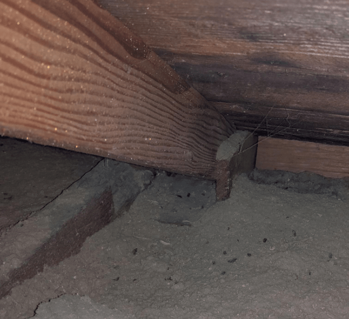
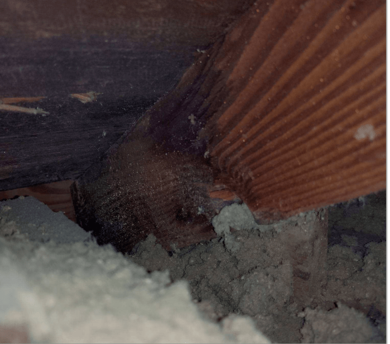
I've just received photos of the roof system, and I'm sorry to say there is no direct load path from the rafter tie to the rafter. How common is this construction type? Guess I'll need to make sure they are both well connected to the top plate.
(Interesting not is the 2x decking used as a roof material)

image_ahxe4l.png


image_hsoo9m.png
 
Bowsers said:
I'm hearing two different answers here now.
A) Model the truss system w/ pin at 1 bottom point
B) Model the system w/ pin at center point.

I would like to clarify that Fletch10 did not state to model with a pin at the center/ridge, he/she said to restrain the ridge horizontally (not vertically). Both of these methods should produce similar results.
 
Oh! I see. Think I would have figured it out when I opened back up the Risa Model.
 
SteelPE said:
chris3eb said:
If you want to know the thrust load, both of your support points should be pinned and the horizontal reaction equals the thrust load. By putting a roller on one end, you are eliminating thrust, but that's not realistic because the connection to the wall is not a roller.

I understand what you are saying, but I am not sure I agree with it. Whenever I model this type of system I have one support as a pin and the other as a roller. I understand the model isn't perfect, but I believe that's as close as I am going to get it

I believe both of these options are valid.
With chris3eb's method, you would model it without the rafter tie, the resultant horizontal reaction is the thrust the rafter tie needs to resist.
With the pin-roller method you would model it with the rafter tie, the resultant axial load in the rafter tie is your thrust
 
Yes, dauwerda is right about what I was saying. I'm now realizing the Bowsers had the horizontal member included in the model, so a pinned end on one side and a roller on the other side would be appropriate.
 
Status
Not open for further replies.

Part and Inventory Search

Sponsor