luiscunha1978
Mechanical
Hi everyone!
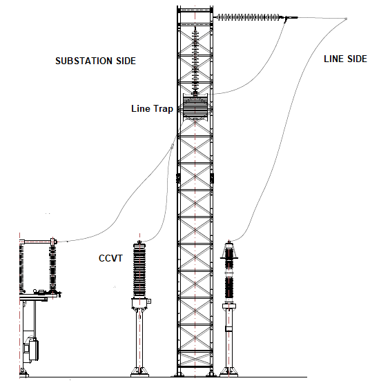
I need help to understand how the below line trap (LT) positioning/mounting will allow the correct functionality of the PLC system. As you can see this is a suspended mounted LT and bellow we have a CCVT:

From my understanding, since the LT blocks the carrier frequency by present a high impedance and a low impendance at the power frequency, the CCVT/Coupling Capacitor should be placed downstream from the LT.
So, I cannot undestand how the depicted picture could allow the correct functionality of the system. Perhaps this is a silly question but I need help to understand this suspension mounted assembly.
Thank you in advanced
I need help to understand how the below line trap (LT) positioning/mounting will allow the correct functionality of the PLC system. As you can see this is a suspended mounted LT and bellow we have a CCVT:

From my understanding, since the LT blocks the carrier frequency by present a high impedance and a low impendance at the power frequency, the CCVT/Coupling Capacitor should be placed downstream from the LT.
So, I cannot undestand how the depicted picture could allow the correct functionality of the system. Perhaps this is a silly question but I need help to understand this suspension mounted assembly.
Thank you in advanced
