Eng-Tips is the largest engineering community on the Internet

Intelligent Work Forums for Engineering Professionals

Wind Loads on Trussed Towers 1

Status
Not open for further replies.

PEFLWI

Structural
Oct 23, 2012
120
0
0
US
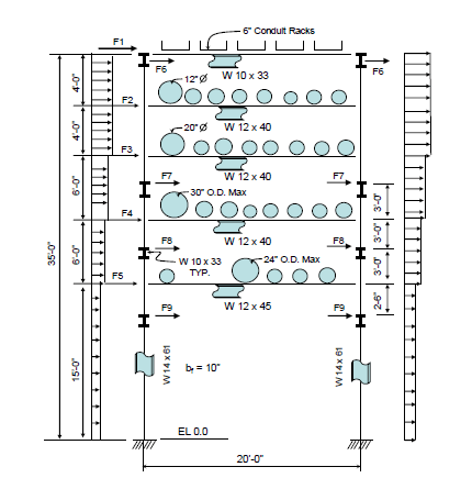
I am working on an analysis of an existing pipe rack. I consider this to be a Trussed Tower type structure (ASCE 7-10) Figure 29.5-3. It seems conservative to me to use the load case where you take 0.75 of the wind load acting simultaneously in the two orthogonal directions (0.75NS + 0.75EW). What do you think?
 
Replies continue below

Recommended for you

You don't have to do it that way. If you show that you have considered multiple load directions. If your tower is rectangular, then considering the 45 degree wind load directions in additional to the orthogonal directions would likely be enough.
 
Where are you getting that load combination? 2.4.1, 6a? (D+0.75L+0.75(0.6W)+0.75Roof)

If so, then I agree it would be inappropriate to apply full wind load to both faces at the same time. Wind can only blow in one direction at a time. It may be prudent to apply a "quartering wind" to the structure, which means it hits the corner of a square building. A simplified load application would involve breaking the wind force into orthogonal components which means you'd have 0.707W applied to each face. So, for the load combination above, you'd have 0.75*0.6*0.707W[sub]NS[/sub] and 0.75+0.6+0.707W[sub]EW[/sub].
 
The combination is part of Ch27 directional procedure. It's not applicable to this situation. The projected area to the wind direction should be used, per Ch29.
 
PEFLWI,

Being in an industry that uses lots of trussed towers and catwalks, a bit of advice: If the tower is all by itself, with no bridges/catwalks running to it, the diagonal wind will control. Don't forget to bump up your wind load for the diagonal by the factor specified in note 4 of Figure 29.5-3.

If you've got a bridge/catwalk running to it, the wind blowing perpendicular to that should control your design - I never check the diagonal wind in that condition.

EDIT:

And there I go again, skimming through the important info in the first sentence. *sigh*

The best deep dive on wind loading (including diagonal) on pipe rack trusses is probably "Wind Loads for Petrochemical and Other Industrial Facilities" by the ASCE. It's a great reference to have. It even includes worked example problems.
 
Note, I am a bit confused here. Pipe rack is a narrow in width, but long in length open steel framing structure, is there any similarity to tower structure except in the sense of open steel framing system? Isn't there a better choice other than tower type for wind?
 
No, there really isn't. ASCE did a survey to compare how engineers in petrochemical facilities operate, and they found that everyone was doing things differently.
 
The use of truss tower for pipe rack seems in line, at least, with the Indian research that says " ASCE 7-05 provides very little, if any guidance for application of wind load for pipe racks. The most appropriate application would be to assume the pipe rack is an open structure and design the structure assuming a design philosophy similar to that of a trussed tower." However, I wonder what ASCE says on its publication "Wind Loads for Petrochemical and Other Industrial Facilities". Link
 
PEFLWI (Structural);

The approach of considering the pipe rack as truss type tower is not correct approach. The combination of wind load acting simultaneously in the two orthogonal directions is applicable for open frame structures rather than pipe racks which are long in one direction. Being experienced d.e. i will propose you to look =Wind Loads and Anchor Bolt Design for Petrochemical Facilities(ASCE) (1997) and PIP structural design criteria at the following link=https://www.pip.org/docs/default-source/practices-documents/stc01015604ba90395a262f789edff00008ddc6a.pdf?sfvrsn=30e9cb9e_0

You are expected to calculate the force per unit length of the piping or cable tray using formula F = qzGCfAf ((29.5-1)
qz = velocity pressure evaluated at height z

Force Coefficients
For structural members Cf = 1.8
For columns Cf = 2.0
For pipes Cf = 0.7
For cable trays Cf = 2.0

Ae is projected Area per foot of pipe rack, Ae = Largest pipe diameter or cable tray height + 10% of pipe rack width.
I have copy and pasted a sample for wind loads for typical pipe rack bent =
wind_loads_for_typical_bent_jo5j7w.png
 
Status
Not open for further replies.
Back
Top