Eng-Tips is the largest engineering community on the Internet

Intelligent Work Forums for Engineering Professionals

  • Congratulations waross on being selected by the Tek-Tips community for having the most helpful posts in the forums last week. Way to Go!

Heillerborg strip method in two way ribbed slab 3

Status
Not open for further replies.

Gus14

Civil/Environmental
Mar 21, 2020
184
0
0
KW
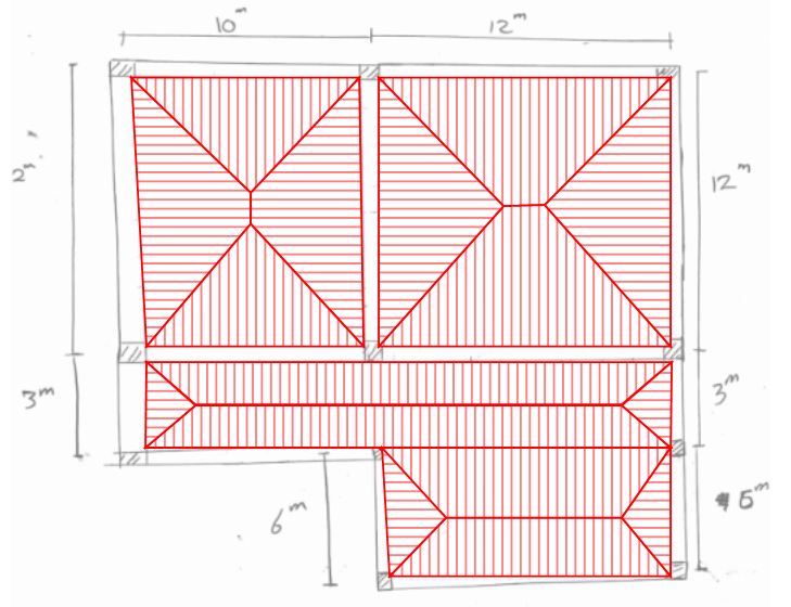
The Direct design method specified by ACI isn't applicable for two way ribbed slab with irregular columns layout.
Is it possible to use loads in each direction from heillerborg strip method (enhanced based on edge condition as in nelson book) and distribute them to the ribs, and then use the ribs reactions to design the main beams?
 
Replies continue below

Recommended for you

Gus14 said:
Is it possible to use loads in each direction from heillerborg strip method (enhanced based on edge condition as in nelson book) and distribute them to the ribs, and then use the ribs reactions to design the main beams?

I don't see any problem with that method so long as you're following the rules associated with it. I feel that you could handle the situation more conveniently, however, by simply assigning loads to your beams using conventional two way slab load distribution assumptions. We can help you with that if you post a sketch of your framing plan. The presence of the ribs will not invalidate such a simplified approach. In fact, the presence of the ribs probably makes the approach more valid because the ribs will diminish the relative influence of slab torsion effects which we typically ignore with hand calculation methods.

How thick is your slab between ribs?

How deep are you ribs (top of slab to bottom of rib)?

 
Thanks for feedback. The heillerbrog strip method seems very powerful especially if the ribbed slab has an opening in it. I drew a random sketch of two ways slabs and one way slabs system. it would be helpful if showed me the " the conventional two way slab distribution". You could assume reasonable topping slab thickness and a rib depth.
 
 https://files.engineering.com/getfile.aspx?folder=6282e783-85ec-4b39-b4fd-c57f8fe49e5a&file=Screenshot_20200412-195512_WhatsApp.jpg
Gus14 said:
it would be helpful if showed me the " the conventional two way slab distribution".

LoadDistribution02.JPG
 

I did know about this method in two way soild slabs. However, recently an experience engineer proved to me that it's inaccurate because in the yeild line analysis method that its based on the area of the trapazoid in front of the middle beam should be larger than the trapazoid area infront of the edge beam. That is because the middle beam acts as continuous support while the the edge beam acts more like a pin support. Any reference to this method origin would be helpful.
 

He proved it on a continuous one way ribbed slab according to the method shown if the slab is one way ribbed slab half of the load should go in to each beam. But using another method by deviding the slab loads on the rib width (to know the loads on each rib) and then design the rib. I can see that more than half the loads from each slab go to middle beam that acts like a continuous support. I explained the calculations in the attached file
 
 https://files.engineering.com/getfile.aspx?folder=7c2c676c-5973-4272-84a3-27c0406603c1&file=Screenshot_20200412-231515_Notebloc.jpg
The yield line method is an upper bound solution which means that the strength derived by that method is the most it could possibly be. The correct yield line pattern must first be correctly guessed.

The Hillerborg strip method provides a lower bound solution. This means that, even if you guess wrongly, the solution by correctly applying the strip method will always give conservative results. Many engineers believe the strip method is to be preferred for that reason.


BA
 
OP said:
However, recently an experience engineer proved to me that it's inaccurate because in the yeild line analysis method that its based on the area of the trapazoid in front of the middle beam should be larger than the trapazoid area infront of the edge beam. That is because the middle beam acts as continuous support while the the edge beam acts more like a pin support.

Yeah, I see what you mean. With very unequal spans there is that effect. Additional thoughs:

1) it's true of slabs with and without the ribs.

2) to an extent, this is only ans true as how you've chosen to reinforce the slabs. In the ULS, things are different with continuous top bar in the short back spans as opposed to a normal top bar / bottom bar disposition.

3) I don't quite get the yield line argument and see no need to resort to it. A regular, elastic analysis will produce the same result.

4) be aware that you've got a very long span beam running right to left in close proximity to a stiff wall running parallel to it. Any analysis performed assuming that beam to be a rigid support for the slab/ribs, is going to be substantially inaccurate owing to the displacements that will occur in the girders in addition to other effects.

Do you have access to finite element software for slab design? If you've got it, that may be your simplest route to something "accurate", at least in the elastic sense.

 
Koot said:
4) be aware that you've got a very long span beam running right to left in close proximity to a stiff wall running parallel to it. Any analysis performed assuming that beam to be a rigid support for the slab/ribs, is going to be substantially inaccurate owing to the displacements that will occur in the girders in addition to other effects.

Scrap that. Upon further inspection, I see that there's a column breaking up that beam span.
 
kootk said:
2) to an extent, this is only ans true as how you've chosen to reinforce the slabs. In the ULS, things are different with continuous top bar in the short back spans as opposed to a normal top bar / bottom bar disposition.
How different ?

kootk said:
I don't quite get the yield line argument and see no need to resort to it. A regular, elastic analysis will produce the same result.
What do you mean by elastic analysis ?


Gus14 said:
How different?

If the rib are not reinforced to be able to deal with atypical moment distributions, those distributions may not be able to develop.

Gus14 said:
What do you mean by elastic analysis ?

An analysis in which internal actions vary linearly with displacements throughout the entire load history. That, in contrast to plastic and other non-linear analyses where you get hinges forming, stiffness changing etc. Elastic analyses are low on the complexity spectrum and, as a result, what most engineers will use to solve most problems unless the nature of the problem is such that it warrants additional complexity in analysis.
 
kootk said:
If the rib are not reinforced to be able to deal with atypical moment distributions, those distributions may not be able to develop
I know this has taken so long but just to make sure I uderstood. Do you mean to design each rib as a simply supported and allow the concrete to crack at the top ? I heard that in old villages people used to put no top rebar in beams or slabs and design each span as simply supported.
 
Gus14 said:
Quote (kootk)
If the rib are not reinforced to be able to deal with atypical moment distributions, those distributions may not be able to develop

I know this has taken so long but just to make sure I understood. Do you mean to design each rib as a simply supported and allow the concrete to crack at the top ? I heard that in old villages people used to put no top rebar in beams or slabs and design each span as simply supported.

Yes, they did. I came across a case like that shortly after I first started to work for an engineering firm in Toronto, Ontario in 1956. No top steel, but bottom steel adequate to serve as simple span reinforcement and the structure had been up there for many years (I forget how many).

It is not a good idea to go quite that far, however, because the negative moment crack could (I have never seen it happen) veer off the support, causing a potential shear failure as well as exhibiting unsightly cracks over the supports. It is desirable to be in the ballpark with the magnitude of positive and negative moments, but it is by no means mandatory to be extremely precise. If in doubt, err on the side of safety. The cost of doing so will be negligible.

BA
 
Gus14 said:
I know this has taken so long but just to make sure I uderstood.

No sweat, this is what we do here.

Gus14 said:
Do you mean to design each rib as a simply supported and allow the concrete to crack at the top ?

Sort of. For the reasons that BAret mentioned, you'd still want some meaningful quantity of top steel at the support for serviceability and to protect your shear capacity. At minimum, I'd put 1/4 to 1/3 of the positive bending steel at the negative region as well.

Another facet of this to consider is that, for the short spans adjacent to long spans, you may develop very high shears within the shorts spans. The backstay effect. I'm not sure if the proportions of your ribs are such that they can be meaningfully shear reinforced. If not, you may need to provide some kind of release for that reason.

 
This is what I'll do:

1. Design the slab as continuous T beam with full floor loads spanning in each direction (blue lines in the linked sketch). Link
2. Design the beams for the tributary load, either one way distribution, or two way distribution (red lines in the sketch).
3. Provide As[sub]min[/sub] for top face of slab, except over the interior supports, for which provide negative reinforcement (top face of slab) as calculated through "1" above.
 
Status
Not open for further replies.
Back
Top