Continue to Site

Eng-Tips is the largest engineering community on the Internet

Intelligent Work Forums for Engineering Professionals

  • Congratulations SE2607 on being selected by the Eng-Tips community for having the most helpful posts in the forums last week. Way to Go!

Multiple coaxial features

Status
Not open for further replies.

Sa-Ro

Industrial
Jul 15, 2019
273
How to define multiple coaxial features for coaxiality with single FCF.

ref attachment.

I used to attach individual Position tolerance FCF to each coaxial features.

Is it possible to use BETWEEN symbol in position tolerance?

Or

Is it possible to use profile tolerance with BETWEEN symbol instead of position tolerance?

If profile tolerance used, will consider linear dimensions which I do not control thru GD&T?
 
 https://files.engineering.com/getfile.aspx?folder=b43c230f-28d8-4704-8e2b-792a3d0864c6&file=IMG_20200415_190855.jpg
Replies continue below

Recommended for you

I assume from your question the combination of profile/position shown is an either/or situation, otherwise its problematic as shown.

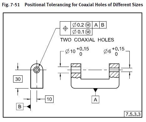
The BETWEEN notation as defined in Y14.5-2009 para 3.3.11 does not specifically limit it to profile tolerances. That said, I don't think it adds any clarity to use it in your case on the position tolerance (in fact, I think it confuses things). Theres nothing wrong with the position tolerances as you have them individually called out but if you wish to group multiple different diameters with the same tolerance one could use the "nX COAXIAL DIAMETERS" or "DIAMETERS INDICATED Y" notation (the latter accompanied by "Y" or whatever letter you choose next to the associated diameters of interest).

Its certainly possible to utilize profile instead of position. The resulting control will be notably different though.*

*Edit - Even more different since the BETWEEN notation A<->B controls all the surfaces between A and B, including those perpendicular to the diameters of interest.
 
Sa-Ro,

I use the between symbol a lot to control outlines of flat plates. This application looks weird to me, but that does not make it wrong. I can interpret it.

The positional tolerance controls the locations of features of size, independently of the size tolerance. Your profile controls everything, including the positions of the flat faces. Your two schemes are not equivalent.

--
JHG
 
It is either any one condition only - position or profile.

So I can mention any identification (letters A - Z symbol #,@) with interested diameters, and denote that letter with single FCF.

Shall I place this single FCF with specified letter in NOTE?
 
SaRo,

Your position tolerances do not completely specify your part. You have to apply diameter tolerances to your round features, and you have to locate the flat faces, by [&pm;][&nbsp;]tolerances, or profiles.

Your profile tolerances do not work until you apply a datum feature to control the position along the axis, such as the left-hand face. This probably is a good idea for the position tolerances too.

Sa-Ro said:
So I can mention any identification (letters A - Z symbol #,@) with interested diameters, and denote that letter with single FCF.

I am not sure what you mean here. Can you re-phrase this?

--
JHG
 
As per chez311 reply

Instead of "DIAMETER INDICATED Y" notation, shall I use A TO Z letters or symbols like #,@
 
For example dia 20 #, dia 15 #, dia 10 #, dia 5 #.

TP|dia 0.1|A - #
 
Sa-Ro,

chez311 is indicating that you can apply a between tolerance to a position tolerance. This works if you have a single long feature, and you need accuracy over only a short portion of it. Position tolerances really should be applied directly to features of size.

You could apply an FCS with an arrow pointing at one of the diameters, then specify something like 4X[&nbsp;]|POS|DIA[&nbsp;]0.1|A|. I think this is ugly.

--
JHG
 
Ok. Thank you.

I will apply FCF to each feature of size.
 
As far as the "between" notation drawoh is correct, that would be one possible way to apply it with a position tolerance. I'm sure there are others, though the one in your OP would not be valid (includes vertical faces which are non FOS). I was simply stating the standard does not limit it to profile tolerances, though you should probably be careful with its use.

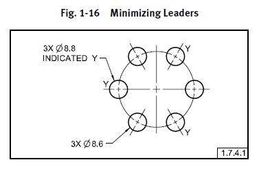
To answer your (15 Apr 20 18:10) question I was talking about the following methods. For the "INDICATED" notation Y14.5-2009 says letters or symbols may be used per para 1.7.4.1 "Where too many leaders would impair the legibility of the drawing, letters or symbols should be used to identify features. See Fig. 1-16.". Numbers are not included in this, likely for good reason as it may be confusing as to whether it should refer to a number of instances.

fig1-16_d4gyp7.jpg


fig7-51_nn6cdj.jpg
 
Status
Not open for further replies.

Part and Inventory Search

Sponsor