kartracer087
Electrical
- Apr 18, 2020
- 64
Hello,
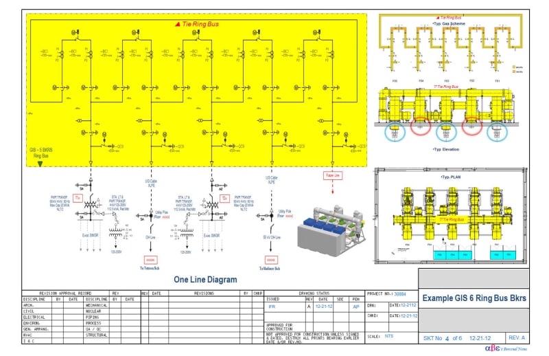
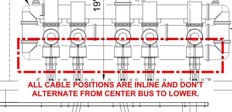
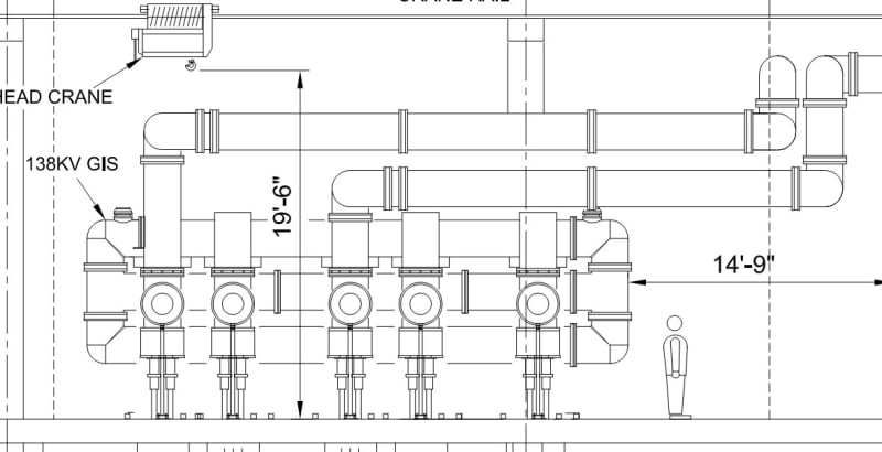
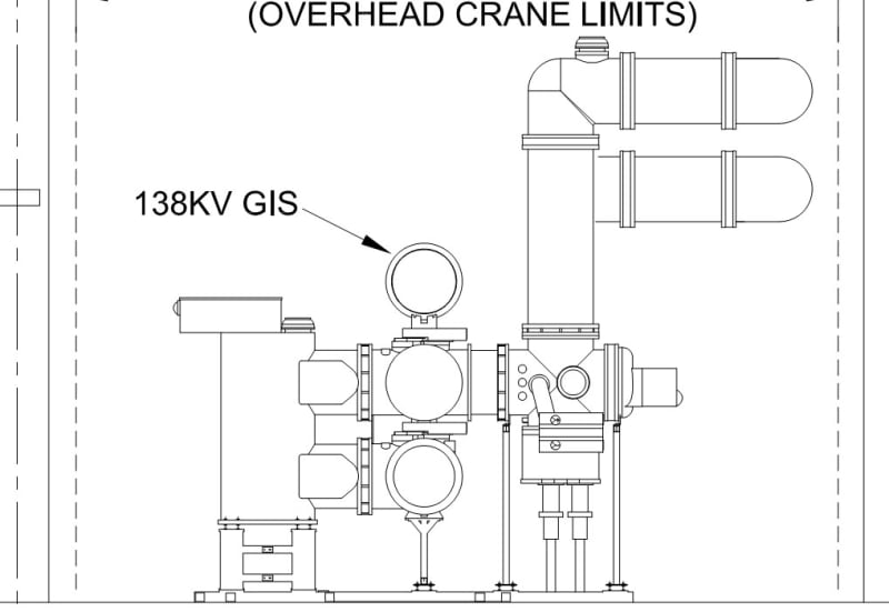
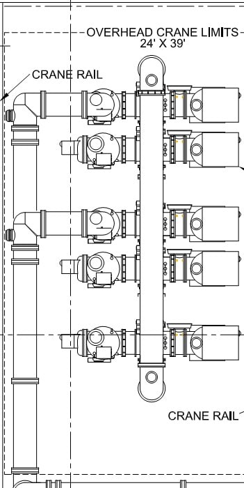
First post here. I've seen a project where the design has planned 138kV GIS in a ring bus arrangment, however, I'm having a difficult time visualizing how this gear is actually configured based on the preliminary public domain drawings. I believe this is ABB's GIS switchgear, however, I have seen it in a different configuration where the cable termination sides alternate between the upper and lower bus positions - I've never seen one configured with all cable terminations in the center position. Possibly someone has a better view of this type of bus configuration? It is a ring bus configuration as I understand.
See pics below for reference.
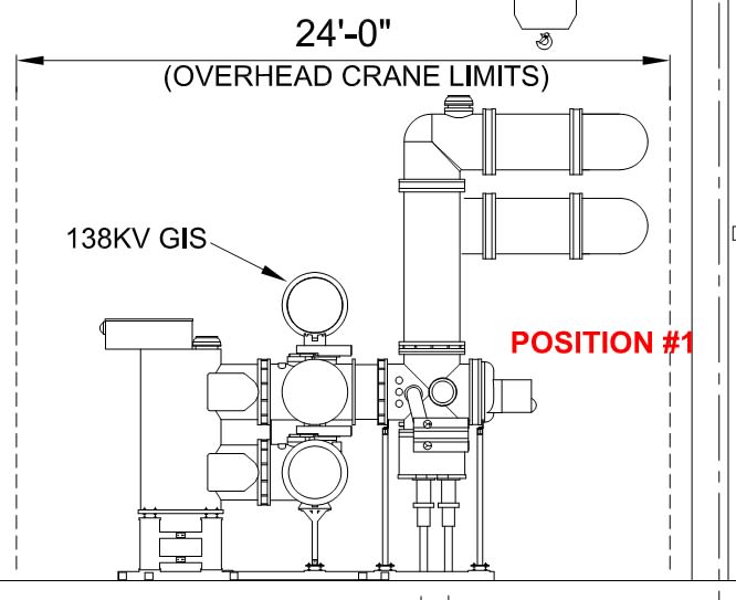
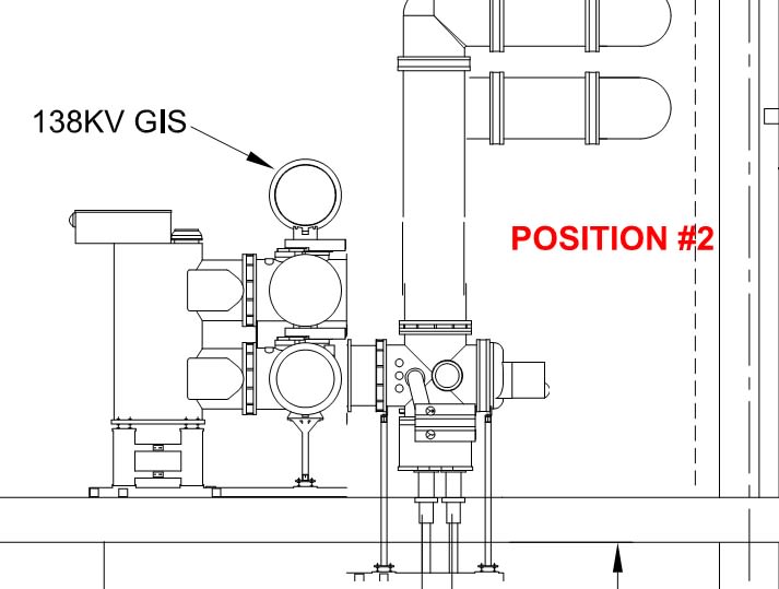
Cable Side Elevation View
Side of the Lineup
Plan View (Top)
Thanks!
First post here. I've seen a project where the design has planned 138kV GIS in a ring bus arrangment, however, I'm having a difficult time visualizing how this gear is actually configured based on the preliminary public domain drawings. I believe this is ABB's GIS switchgear, however, I have seen it in a different configuration where the cable termination sides alternate between the upper and lower bus positions - I've never seen one configured with all cable terminations in the center position. Possibly someone has a better view of this type of bus configuration? It is a ring bus configuration as I understand.
See pics below for reference.
Cable Side Elevation View

Side of the Lineup

Plan View (Top)

Thanks!

