Continue to Site

Eng-Tips is the largest engineering community on the Internet

Intelligent Work Forums for Engineering Professionals

  • Congratulations KootK on being selected by the Eng-Tips community for having the most helpful posts in the forums last week. Way to Go!

Three-Segment Composite Tolerances 1

Status
Not open for further replies.

Rwelch9

Mechanical
Apr 22, 2020
116
Hi guys,

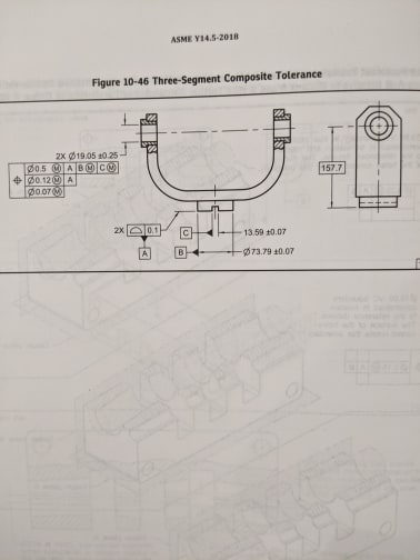
looking at the attached drawing,

Could anyone explain how three-segment composite tolerances work.

Where i fall short is just the general use of the positional symbol .

I have always seen perpendicular or parallel. So just trying to get familiar with using position to control the parallelism or perpendicularity etc.

So the top segment locates the features on the part . ( the 157.7 basic dimension ) in this drawing example to locate the coaxial cylinders to Datum Features B and C would this control the perpendicularity or is there a basic dimension there ( zero ? )

2nd segment = does this ensure the axis of the Ø19.05 is parallel to A.

3rd segment = Does this control the true position between the two Ø19.05


Thanks


Ross


Replies continue below

Recommended for you

IMG_20200501_195757_gcxpnu.jpg
 
You need to push the button that adds the link after you upload.

Ahh - you fixed it.
 
For Composite Position Tolerance the first segment (PLTZF) constrains LOCATION AND ORIENTATION to specified datum features.

Second and all lower segments (FRTZF) constrains ORIENTATION ONLY to specified datum features.

Location and orientation between all features in the pattern is always fixed at basic no matter the datum feature reference, unless otherwise noted. There are several figures preceding the one you attached that show this relationship pretty well.
 
chez311,

perfect much appreciated.


to recap .

segment 1 = Datum C ( mid plane of the slot ) is this controlling perpendicularity between the 2x Ø19.05 axis and the mid plane of Datum C

Segment 2= is controlling the 2x Ø19.05 axis orientation tighter to Datum A.

was i correct with the last segment with no Datum . ( would you check this by checking the true position from 1 Ø19.05 cylinder to another ?
 
segment 1 = Datum C ( mid plane of the slot ) is this controlling perpendicularity between the 2x Ø19.05 axis and the mid plane of Datum C

No, well not quite at least. Assume x and z are parallel to the page on the view on the left, and y is coming out of the page. The first segment being the PLTZF means the 2x 0.5 position tolerance zones for the holes is constrained in location (x,y,z) and rotation (u,v,w) with respect to |A|B(M)|C(M)| as well as fixed in basic orientation/location relative to one another.

The second segment means the 2x 0.12 position tolerance zones are constrained in rotation (u,v) with respect to |A|. This is not equivalent to orientation/parallelism to |A| since the 2x 0.12 tolerance zones are still fixed in basic orientation/location to each other - parallelism would not require the pattern of 2x holes to have a fixed location relationship to each other.

The last segment means the 2x 0.07 position tolerance zones are not constrained in location or rotation with respect to any datum features. These 2x 0.07 tolerance zones are still fixed in basic orientation/location relative to one another.

All of these must be satisfied in order for the features to pass.
 
Status
Not open for further replies.

Part and Inventory Search

Sponsor