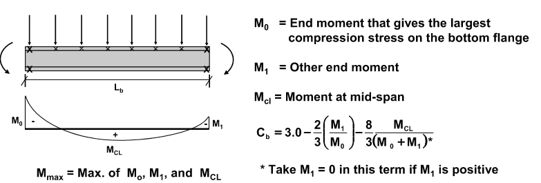
When using Yura's Cb Equation below (with continuous top flange lateral support), do you limit Cb to some maximum value?
I am checking some existing beams continuous over columns whose moment gradients results in Cb with values ranging from 3 to 4.
As a side note, in CSA S16, the omega sub 2 factor (Canadian counterpart of Cb factor),it is limited to 2.5 - but I understand that the expression given in there assumes top and bottom flange of the beam are both laterally unsupported throughout the unbraced length of the beam.
Looking forward to hear what the more experienced folks in here think.
Thanks in advance.