Continue to Site

Eng-Tips is the largest engineering community on the Internet

Intelligent Work Forums for Engineering Professionals

  • Congratulations KootK on being selected by the Eng-Tips community for having the most helpful posts in the forums last week. Way to Go!

Using Position to control perpendicularity 1

Status
Not open for further replies.

Rwelch9

Mechanical
Apr 22, 2020
116
Perpendicul_variations_olfswi.jpg


Hi ,

Whilst doing some research on the internet ( which can do more harm than good ) i did read with the Y14.5 2009 standard simultaneous requirements is not currently applied to orientation.

Anyone who has seen my previous threads about controlling two set of coaxial cylinders has been an issue for me.

Can you use the position symbol to control perpendicularity.

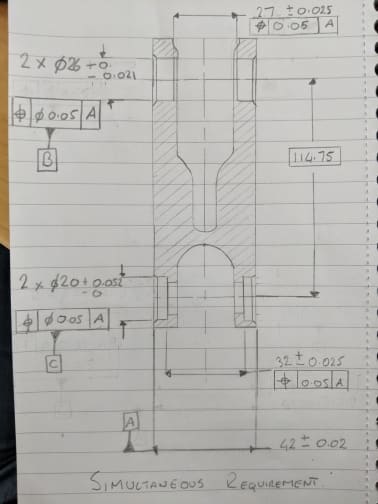
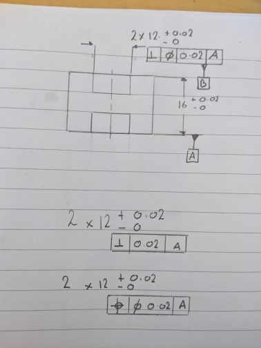
see my basic drawing below.

Datum A is the mid plane the we have two coaxial cylinder pockets .

What would be the best use of tolerance to control the position between the two pockets and the orientation to Datum A.

What is the main difference between the 3 sets of suggestions i have used.

Thanks


Ross
 
Replies continue below

Recommended for you

Whilst doing some research on the internet ( which can do more harm than good ) i did read with the Y14.5 2009 standard simultaneous requirements is not currently applied to orientation.

Correct with both 2009 and 2018, it does not apply by default however I have seen it suggested that you could invoke it with a specific note - however I'm not sure if thats universally accepted. It makes little difference in your case though, I can't see there being much variation if they are held separately or simultaneously.

Can you use the position symbol to control perpendicularity.

I think I answered this before. Position will limit orientation, but also location.

Datum A is the mid plane the we have two coaxial cylinder pockets .

That might be your intent, but its not suggested by the way its drawn. Your datum feature symbol needs to be inline with the width dimension if thats how you want it to be interpreted.

What would be the best use of tolerance to control the position between the two pockets and the orientation to Datum A.

....position....

What is the main difference between the 3 sets of suggestions i have used.

1) 2x |perpendicularity| dia 0.02 | A | *(note the diameter symbol should be in the same box as the 0.02 tolerance)*
2) 2x |perpendicularity| 0.02 | A |
3) 2x |position| dia 0.02 | A |

1) Controls orientation within a 0.02 diameter tolerance zone to A
2) Omission of the diameter symbol controls orientation within a width shaped (planar) 0.02 wide tolerance zone. I don't think this is what you want, and if you do you're missing the designation in the other direction - this is typically used if you want to allow more variation in one direction than another. Theres no examples of this utilized with orientation, however Y14.5-2009 fig 7-28 (Y14.5-2018 fig 10-29) shows it with position.
3) Controls orientation and location within a 0.02 diameter tolerance zone to A
 
simultaneous_requirments_2_jjhm9n.jpg


Is 1 + 3 basically the same then

or is 1 checking the axis of the pockets to them plane and the other is checking the plane to the axis of the pockets.?

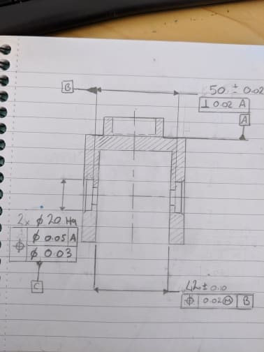
using this to go back to my previous drawing .

is this call out technically not to the book regarding trying to use simultaneous requirements to control both coaxial pockets orientation to A.

Greenimi suggested in my previous thread there was not much use for Datum B and C .

However in the rest of the part some features are tied to these datum Features . So does this then make the call out of Datum B and C okay
 
Is 1 + 3 basically the same then

or is 1 checking the axis of the pockets to them plane and the other is checking the plane to the axis of the pockets.?

No. (1) is perpendicularity (orientation). (3) is position. How do you believe they can they be the same?

is this call out technically not to the book regarding trying to use simultaneous requirements to control both coaxial pockets orientation to A.

I see where there may be some confusion. You'll notice that angularity, perpendicularity, and parallelism are "Tolerances of Orientation" and position is a "Tolerance of Location" (which may confuse you a bit - since position controls both location and orientation) - hence why your question of "does simultaneous requirements apply to orientation" as well as combined with a 2x perpendicularity control in your OP I was inclined to answer "no". Simultaneous requirements, when applicable to a position or profile tolerance, is applicable to any control of orientation those tolerances might provide. It just doesn't apply by default to "Tolerances of Orientation" aka angularity, perpendicularity, and parallelism.

You may want to review the applicable sections and figures on simultaneous requirements, for example the excerpt below from 2018 (similar section in Y14.5-2009 para 4.19). There is also additional information contained in the sections on position and profile on how it applies specifically to those two concepts.

Y14.5-2018 said:
7.19 SIMULTANEOUS REQUIREMENTS
A simultaneous requirement applies to position and profile tolerances that are located by basic dimensions related to common datum features referenced in the same order of precedence at the same boundary conditions. In a simultaneous requirement, there is no translation or rotation between the datum reference frames of the included geometric tolerances, thus creating a single pattern.

However in the rest of the part some features are tied to these datum Features . So does this then make the call out of Datum B and C okay

If its referenced in another FCF it may be okay. To greenimi's point - I wouldn't extrapolate out and say its a valid or correct use without seeing exactly how its utilized.
 
OP said:
there was not much use for Datum B and C .

Yes, there is not much use of B and C in the context shown. Do not extrapolate to other parts of the drawings, other features we've NEVER seen (either in this discussion or other threads).
 
chez311

just as we are talking about position also controlling perpendicular.

so yes they are different however they can be used to control the same thing ?

with my 1st sketch tolerance example No1 . yes it has to be perpendicular but for this to happen the position between the two pockets would have to be good ?

thus my suggestion that 1 and 3 although different can effectively produce the same outcome ?

i will look into the suggested examples in the book

thanks


Greenimi

apologies i know i am asking for some advice and help whilst giving you guys half or false information. you knowledge and help is appreciated,

 
Rwelch9,

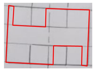
See the picture below. The geometry shown in red will meet your tolerance no. 1 from the 1st sketch, but will not meet tolerance #3. I will repeat myself from the other thread:
pmarc said:
-- Yes, in addition to being a perpendicularity control relative to A, the position applied to 2 datum features B will also control axes offset. Perpendicularity tolerance alone is not capable of controlling the latter.

Also, not sure why in your 1st sketch the diameter symbols are used in 1 and 3, if the features are slots, not cylindrical holes.

capt_jognc5.jpg
 
pmarc

so my 1st tolerance example . i forgot a vital piece of information the diameter symbol as you spotted. So my intent is to have 2 coaxial pockets thus why i stated 2x .

Does my 1st tolerance however have no control over the position between the two pockets two each other.

My thoughts were from you red line drawing . if i constructed a center line from one pocket to the next and they were out by that much on the red line drawing . the perpendicularity would be way off.

My 1st sketch is terrible to be honest , i had the Datum Symbol in the wrong place to create a Datum center plane and i forgot the Ø symbol before the 12.


Thanks

Ross


with my 1st sketch tolerance example No1 . yes it has to be perpendicular but for this to happen the position between the two pockets would have to be good ?

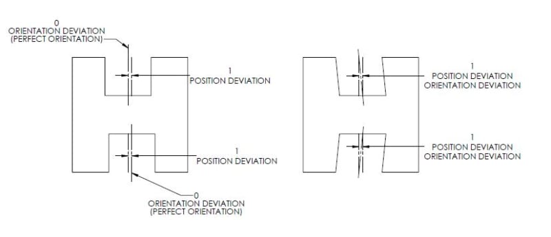
I'm not sure if it adds much to pmarc's figure but I had already sketched out something quick so I figured I would post it. The two pockets can have perfect orientation but have significant position deviation.

POSITION_VS_ORIENTATION_fopdwm.jpg
 
chez311

I do completely understand this concept although what i have clearly done wrong is state that my intent was to have the common axis between the two pockets as my Datum ?

so i wouldn't be checking 1 pocket individually i would be checking the common axis between them . However i do not think i have got the quite correct with my drawing ?
 
Okay, thanks for the clarification on missing diameter.

Both tolerances, either perpendicularity or position, require each individual axis to reside either in perpendicularity or position tolerance zone. The fact that you put 2X does not mean that the requirement applies to an axis established from both features.

In the perpendicularity case, the two tolerance zones have to be perpendicular to the datum center plane A. And that's all.

In the position case, the two tolerance zones have to be perpendicular to the datum center plane A, but also coaxial with each other.
 
so i wouldn't be checking 1 pocket individually i would be checking the common axis between them

No, they would be treated as a pattern of individual features. Separate or interrupted features will not be treated as a single feature unless the Continuous Feature <CF> symbol is utilized.*

*Edit - or an equivalent note to the same effect.
 
thanks for the great answers .

i few very basic concepts i really have been miss understanding.

for the bigger sketch i did with two sets of coaxial cylinders. i assumed the way i dimensioned them was to create a center line between the two cylinders and that was the datum ?


In my smaller sketch where would Datum B come from as i assumed again it was the axis derived from the two pockets together.

Thanks

Ross
 
for the bigger sketch i did with two sets of coaxial cylinders. i assumed the way i dimensioned them was to create a center line between the two cylinders and that was the datum ?


In my smaller sketch where would Datum B come from as i assumed again it was the axis derived from the two pockets together.

Without going too deep into the weeds, determining conformance of a feature and establishing tolerance zones has notable differences from deriving/establishing datum features.

Perhaps pmarc can put it a bit more completely and succinctly than I, however I'll take a shot at it without going off the deep end:

While a tolerance zone establishes the boundary within which a feature's surface or derived axis/center plane must fall within (or sometimes, as in MMC surface interpretation, a volume/boundary which may not be violated), simulation of a datum feature is defined by contact and the relationship between a datum feature and its simulator.

Thus - while a 2X RFS position tolerance establishes 2X tolerance zones within which the separate axes must fall, the datum feature derived from these 2X pockets would consist of 2X expandable simulators that share a common axis as unless otherwise noted (or freed from this requirement through the datum translation symbol) datum feature simulators are fixed at basic location (0 in this case) and orientation (0deg/180deg in this case)*. This concept can be extrapolated to other patterns of holes of nonzero basic location and of any basic orientation, of which coaxial cylinders could be considered a special case. For RFS these simulators are expanded simultaneously. The fact that this special case establishes a unique and easily defined axis is actually less important than the aforementioned relationship between datum feature and simulator.

*Edit - to add, this requirement of basic location/orientation unless otherwise specified is regardless of any tolerances applied to a feature. Even if there is no position tolerance applied to a pair of holes, if they are utilized as a datum feature their simulators are still technically required to be at basic location/orientation unless otherwise specified even if the resultant part had so much variation that you couldn't physically fit the part on the simulators. Obviously this would be a failure on the part of the designer and a poorly specified part, but I'm just using it as an extreme case.
 
chez311

unfortunately as i think you were trying to hint , i need it very much simplified at the moment for the level of understanding i have of the core concepts.

If we take my small sketch and regardless of how it was dimensioned , just as an example.

Datum A = Mid plane .

Datum B=

There are three ways i think i know of to Datum these pockets

1= top pocket would be Datum B , this would in turn require the bottom pocket to positionally accurate back to the top pocket.

2= the opposite of above

3= create an axis between the pockets and use that as the datum.


If a part is symmetrical is it okay to just pick a side to use and create a datum reference frame off one side of your choice and then use position for the other side to the tie the location and orientation.

regarding option 3

Is there only two ways to create a common axis between to pocket features .

1= use a CF symbol

2= call one datum B then the other datum c and use B-C as a common datum axis ?


If a designer as the intent of two pockets to be coaxial , however they are two feature so error of somewhat regardless of how little will be there.

Do you always have to specify just how much the two pockets in this can be out to each other . ( you cannot just say they are coaxial but not put any limit on how much they can be out to one another.

Thanks

Ross


The standard spends a lot of time on types of theoretical geometry derived from different configurations of datum features and where this theoretical geometry is, to the point that I've seen designers think they actually have to point out where a datum axis or center plane is with a leader line and a note. This is really less important, and in most cases arbitrary, (not to mention improper unless in the form of Y14.5-2018 fig 7-56 for a customized DRF) than as I said the relationship between a datum feature and its simulator and how it constrains your degrees of freedom.

Imagine if a bolt circle of 4X holes was datum feature B and a flat perpendicular face was datum feature A. Another feature could be held wrt |A|B| without any concern with where the derived pair of orthogonal datum planes/axes are. Does it coincide at the axis of one of the 4X holes? Is it in the middle of all 4X at the center of your bolt circle/point of symmetry? Who cares - what you're really concerned with is that A constrains (u,v,z) and B constrains (w,x,y). Specifying a unique axis does not change this fact.

In regards to your options, I'll condense it to the few below - and keep in mind what I said previously that establishing conformance of a feature and simulation as a datum feature are two quite different concepts. Theres a very good reason why the standard differentiates between RFS/MMC/LMC as material modifiers on geometric tolerances and RMB/MMB/LMB as material boundary modifiers on datum feature references.

1) 2X pattern of holes specified as datum feature B
2) Each hole individually specified as separate datum features (say B and C) and then referenced B-C
3) The pair of holes controlled with <CF> and specified datum feature B

I believe (1) and (2) result in identical simulators and simulator behavior as specification of the multiple datum feature B-C indicates that both datum features B and C have the same precedence, as if they were a part of a single pattern. Whether or not (3) results in different behavior depends on how one interprets "simultaneous" expansion/contraction of simulators per Y14.5-2018 para 7.12.4 (Y14.5-2009 para 4.12.4), at least for RMB, but I think thats getting lost in the weeds a bit. Even so, for (3) I believe that unless theres a case of extreme size/form error between the features even depending on one's interpretation of "simultaneous" I think the differences in most cases would be very small. Its worth noting that features controlled with <CF>, since they are literally treated as a single feature, do not require (and indeed I believe it would nonsensical to apply) a position tolerance to control relative coaxiality.*

*Edit - I should clarify this, a position tolerance may certainly be applied (as I did in the example in my later post) but it not longer limits coaxiality of the 2x holes since they are considered one (albeit interrupted) feature.
 
2x_pattern_ej5qkl.jpg

Chez311


One thing i am confused with especially is your option 1) 2x pattern of holes specified as datum B.

See drawing attached i have 2x Ø20 which is Datum C
Does this mean the axis derived between the two pockets is the Datum feature B ?


Also with the two pockets in my sketch which i have called datum C
Having datum C positionally good to A ( should this Datum C positionally be good to Datum B to ensure the cylindrical pockets are perpendicular to Datum B also )

Thanks

Ross
 
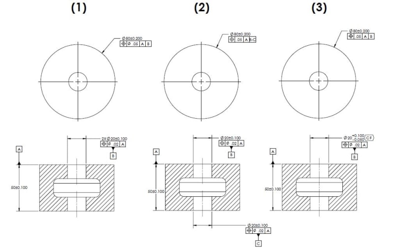
I think the introduction of another figure, while I know you are trying to apply it to your drawing, confuses things a bit. I'm going to simplify it and utilize an extrapolation of the figure contained in your OP. Below is what I envisioned for my cases 1-3.

PATTERN_OF_RMB_k1ofkg.jpg


Does this mean the axis derived between the two pockets is the Datum feature B ?

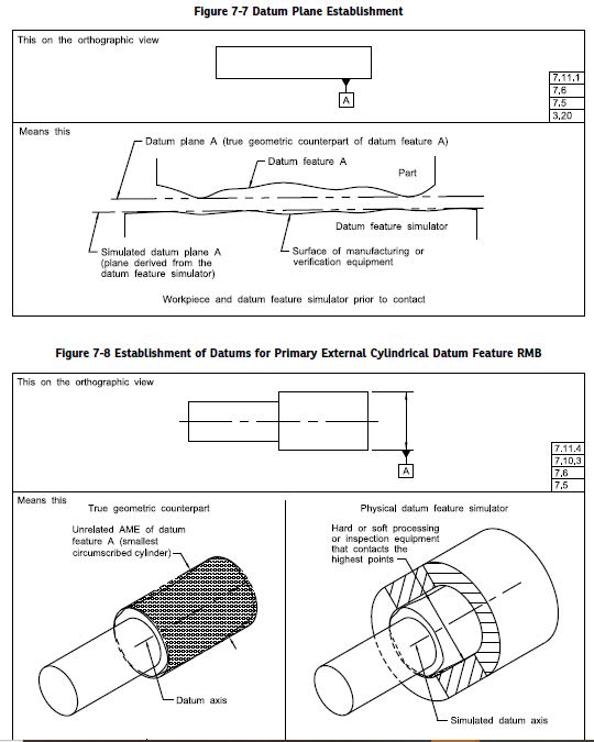
I would also familiarize yourself with terms contained in the standard for the difference between a datum, datum feature, datum feature simulator, etc.. The below figure and accompanying text might help, among others.

FIG_7-7_yow2zp.jpg
 
chez311

my problem with a datum and the use of a datum feature simulator is lost.

This is due to the fact as previously stated my 1st choice of measurement is a CMM.

so take your drawing 1 for example.

I would measure these pockets on the CMM , that why i says things like is the datum derived from the axis between the two pockets.

The use of an actual Datum simulator rather than a virtual simulator created by CMM software.

Again referring to your drawing example 1 . ( 2x pattern of holes specified as Datum feature B )

to check the part you showed i could sit the part up on it side . this would allow me to index the CMM probe head at 90° either side and take these holes as cylinders . this would allow me to check these cylinders to each other , check the perpendicularity of each to datum feature A. etc etc.

The use of actual datum simulators never has been showing to me and is maybe why my core understanding of a Datum is wrong.

 
It doesn't matter if your simulators are physical or virtual, the concept is the same. The differences between them are how they are formed, not how they behave.

Again referring to your drawing example 1 . ( 2x pattern of holes specified as Datum feature B )

to check the part you showed i could sit the part up on it side . this would allow me to index the CMM probe head at 90° either side and take these holes as cylinders . this would allow me to check these cylinders to each other , check the perpendicularity of each to datum feature A. etc etc.

In my example (1) there is no need to separately check the cylinders for position to each other and perpendicularity to A. The 2X position tolerance to |A| establishes a pair of tolerance zones at 0 basic location relative to each other and 90deg basic orientation to A. The holes should then be probed with a sufficient number of points to establish a repeatable UAME. The axis of each hole's UAME must both fall within this basically oriented/located tolerance zone simultaneously. This limits each hole's position relative to each other and perpendicularity relative to A without having to be verified separately.
 
Status
Not open for further replies.

Part and Inventory Search

Sponsor