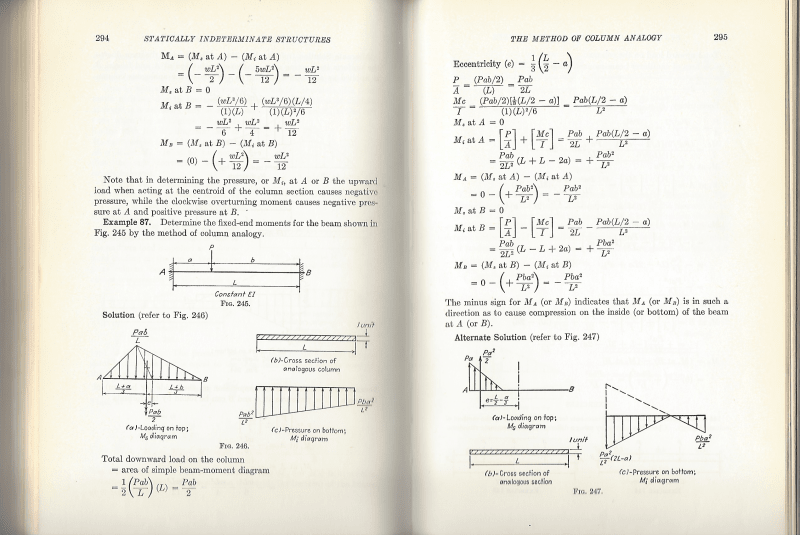
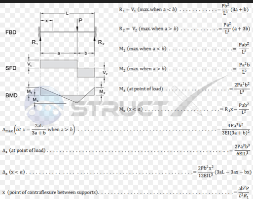
Does anyone have the derivation procedure for deflection formula of a clamped-clamped beam as shown in attached figure.
Navigation
Install the app
How to install the app on iOS
Follow along with the video below to see how to install our site as a web app on your home screen.
Note: This feature may not be available in some browsers.
More options
Style variation
-
Congratulations MintJulep on being selected by the Eng-Tips community for having the most helpful posts in the forums last week. Way to Go!
You are using an out of date browser. It may not display this or other websites correctly.
You should upgrade or use an alternative browser.
You should upgrade or use an alternative browser.
Derivation of deflection at any point formula for a clamped - clamped beam 2
- Thread starter Vimukthi
- Start date
- Status
- Not open for further replies.
you could derive it by hand … the problem is doubly redundant but not impossible (nor very difficult) to solve.
the other tack would be the model the fixed ends with the moments that you can find in Roark, solving the redundancy for you, and work through the math … SF(x) > BM(x) > v(x) > d(x) … integrating the BM equation.
another day in paradise, or is paradise one day closer ?
the other tack would be the model the fixed ends with the moments that you can find in Roark, solving the redundancy for you, and work through the math … SF(x) > BM(x) > v(x) > d(x) … integrating the BM equation.
another day in paradise, or is paradise one day closer ?
You could start off with a simple beam, calculate the moment, Pab/L.
Calculate area under the M/EI curve which is (Pab/L)*L/2EI = Pab/2EI
Find c.g. of the moment curve (or the M/EI curve) = (0+a+L)/3 = (a+L)/3 or (2a+b)/3
Find slope at ends of beam, namely reaction of M/EI curve treated as load.
Slope A = (Pab/2EI)(a+2b)/3L = Pab(a+2b)/6EIL
Slope B = Pab(2a+b)/6EIL
Consider moment applied at A
Ma/EI varies from Ma down to 0. Area under Ma/EI curve = MaL/2EI
Similarly for moment applied at B, Area under Mb/EI curve = MbL/2EI
Solve for Ma and Mb such that slope A and slope B = 0
Calculate deflection in the usual way, knowing Ma, Mb and shape of moment curve.
BA
-
1
- #4
You need to define what is a "clamp" in your thought. To me, a clamped support has no degree of freedom, so a beam with clamped ends behave the same as the fixed end beam. You can prove me wrong, then you need to show a physical example of clamped support.
-
1
- #7
- Thread starter
- #8
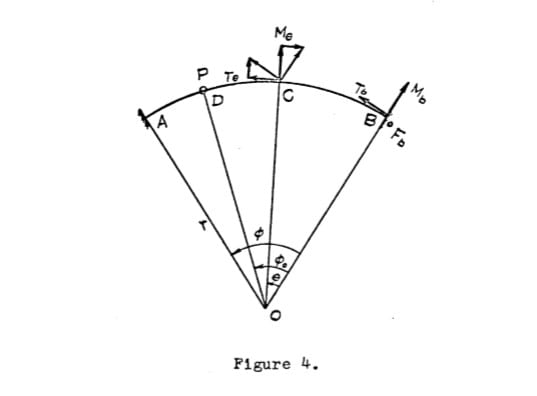
Thanks for all of your replies. I was able to find the support reactions easily by applying Castigliano's theorem. and then as rb1957 said integrating starting from v(x) solves the problem. But the main problem I was trying to solve was the deflection of fix-fix CURVED beam, which I'm not sure that integrating from v(x)is correct. The moment area method can be applied as shown in the attached figure. but here ∅/2 means the centroid has to be at the mid span right? or Am I correct that it is actually the distance to the centroid? If so, to find the deflection for a system with a load at random location I just have to replace the ∅/2 with correct radial distance to centroid right?
- Thread starter
- #9
I believe you can also use superposition if you know a few perhaps more common relationships already. If you know the deflection and end slope of a simply supported beam, and the deflection of a beam with one end fixed under an imposed rotation at the free end (being the end rotation of the simply supported span). Add together all the individual formulas for these cases to give you the exact formula:-
Simply supported span deflection under your imposed loading.
Same end rotation as simply supported span imposed at ends of a one end fixed span (to give no net rotation). Repeat for both ends.
Simply supported span deflection under your imposed loading.
Same end rotation as simply supported span imposed at ends of a one end fixed span (to give no net rotation). Repeat for both ends.
Actually, forget what I said, only works for straight member. Didn't read your repl right above about a curved beam.
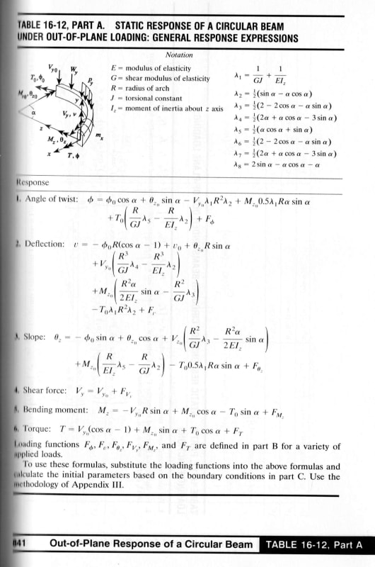
EDIT - maybe this is of use. The only change to the integrals is that for a curved beam dx = rdθ
EDIT - maybe this is of use. The only change to the integrals is that for a curved beam dx = rdθ
- Thread starter
- #12
Forgot to tell its a horizontally curved beam. And gonna try superposition method also after trying moment area method to verify. Also for superposition can I use pin-pin with load and pin-pin with imposed end rotations instead of pin-fix as u suggested?
For a curved beam I really think a frame analysis with short straight members is the easiest, and probably most accurate, way to go.
Doug Jenkins
Interactive Design Services
Doug Jenkins
Interactive Design Services
- Thread starter
- #15
thx for leaving out critical information !
I think trying to hand calc the deflected shape will fail. I think the interaction between the two section moments will make this difficult for all but the simplest sections.
I'd use FEA.
another day in paradise, or is paradise one day closer ?
I think trying to hand calc the deflected shape will fail. I think the interaction between the two section moments will make this difficult for all but the simplest sections.
I'd use FEA.
another day in paradise, or is paradise one day closer ?
- Thread starter
- #19
@rb1957 No I initially wanted to study the derivation of fixed straight beam and then moved on to curved beams. In the book that roby suggested has everything I need. But seems like there's no derivation in it so I can study it. I will use FEA (abaqus) later but for now I just need to study it in a theoretical level.
@agent666 I solved it using superposition. Don't know if it is correct but I can verify it using expressions that roby suggested.
Thank you all for your time!
@agent666 I solved it using superposition. Don't know if it is correct but I can verify it using expressions that roby suggested.
Thank you all for your time!
Vimukthi said:I will use FEA (abaqus) later but for now I just need to study it in a theoretical level.
Seems like overkill to me. One of the nice things about analysing relatively simple systems with a frame analysis is that you get clear graphs of member actions along the length of the beam, that you can relate back to fundamental beam bending theory.
Doug Jenkins
Interactive Design Services
- Status
- Not open for further replies.
Similar threads
- Locked
- Question
- Replies
- 6
- Views
- 3K
- Replies
- 2
- Views
- 2K
- Question
- Replies
- 3
- Views
- 8K
- Question
- Replies
- 6
- Views
- 7K


