Continue to Site

Eng-Tips is the largest engineering community on the Internet

Intelligent Work Forums for Engineering Professionals

  • Congratulations KootK on being selected by the Eng-Tips community for having the most helpful posts in the forums last week. Way to Go!

Weird reactions in bored piers due to wall offset

Status
Not open for further replies.

RD2EN

Structural
Oct 25, 2019
12
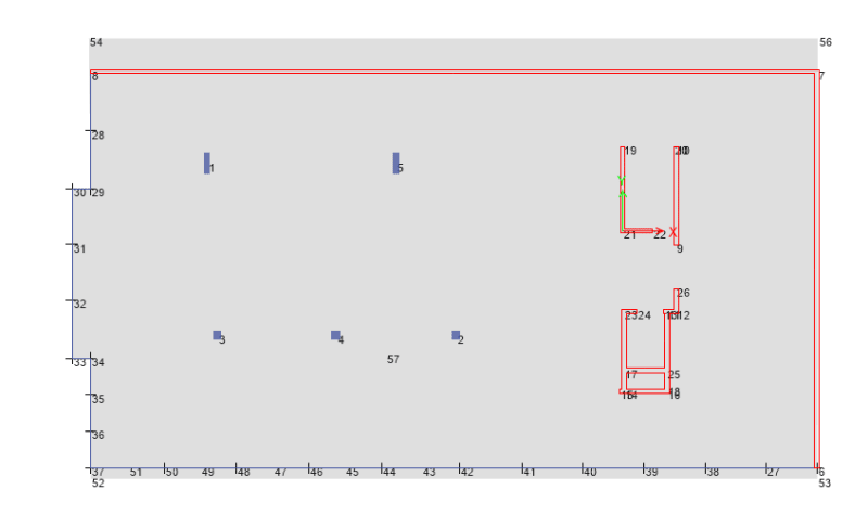
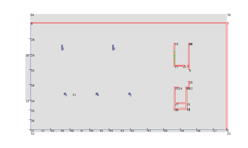
Below is the screenshot of a basement I did and I have done some simplified hand calculation on the bored piers design by making the left hand side 'capping beam - shotcrete wall' straight instead of offset as shown and then when I use FEA analysis I realise that the reactions at the corner differ greatly from my simplified computation! (capping beams are assigned with pin restraints)
full_tziprt.png

1221_oocn0u.png

m12_bx0vyx.png


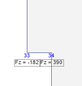
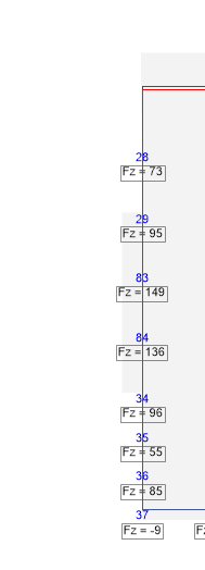
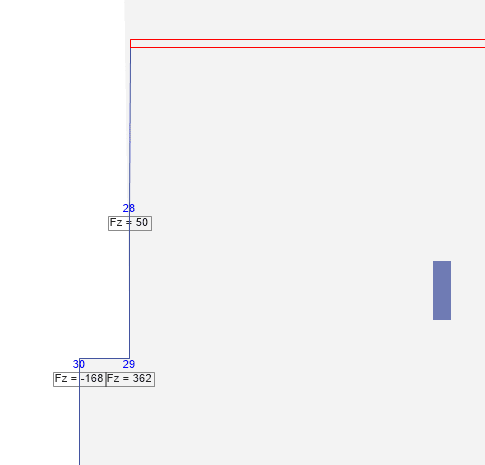
The above are the results that FEA gives me. As you can see, corner point 29 & 34 has way higher reactions than others and point 30 and 33 are in tension.

Below illustrates what my simplified computation was based on.
full2_q9ads0.png

normal_odelm7.png


Can anyone tell me why is that so and what to do if I already designed it as simplified method by making it straight and they already start the construction? (I didn't use FEA back then)
 
Replies continue below

Recommended for you

What units are you using for reactions? Kips?

How can there be large tensile forces at Nodes 30 and 33? And such large reactions at Nodes 29 and 34? It makes no sense. Looks like you have misinterpreted the software you are attempting to use.

For the time being, I would be inclined to go with the simplified computations you made originally, but to be on the safe side, ask your boss to have a quick look over the reactions you calculated. Bosses can sometimes see things at a glance that others may overlook.

BA
 
Your layout is highly irregular, which is prone to causing error in finite element analysis. What are the elements from joints 6-7 & 7-8? And why there are dual joints 6/53 and 37/52? How the joints been connected? Do you have slab in the model? You need to exam the result on every joint, do they make sense (match your estimate)?
 
The wall above your peirs looks like it is acting as a moment bracing wall, giving a coupling effect in the peir reactions below. If you have included shrinkage effects and temp in your analysis, it is likely that these walls are restraints to these effects. There would be an issue in this layout that these returns do attract forces and detailing should be used to stop these from being a restraint. Don't know enough about the building but some ideas are a slip joint between the slab and wall.

"Programming today is a race between software engineers striving to build bigger and better idiot-proof programs, and the Universe trying to produce bigger and better idiots. So far, the Universe is winning."
 
The units are all in kN.
That's why I get confused.

They are normal 150mm walls below. And I do have slab in the model.

I didn't include shrinkage or temp in the model.

I still cannot figure out why so I have upload the Etabs model.Link Can anyone please have a look?


 https://files.engineering.com/getfile.aspx?folder=3f11e598-5ccc-4c54-be4d-7e43c732d06f&file=Model1.EDB
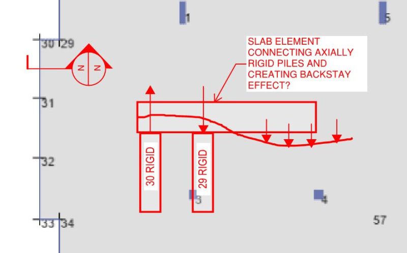
I don't understand this. So you are saying that the internal slab is being cantilevered by these two piers and thus making the loads on external piers to be uplift? What if I treat them as one support like normal as what I simplified? what will happen? This is killing my monkey brain now as the detention has been constructed.
 
OP said:
I don't understand this. So you are saying that the internal slab is being cantilevered by these two piers and thus making the loads on external piers to be uplift?

Sounds like you understand the concept perfectly. Only you can determine if the concept truly reflects what's going on in your model though. How thick is your slab? Can you output local moments and shears in that area? Are your piles modelled as axial springs or rigid supports?

OP said:
What if I treat them as one support like normal as what I simplified? what will happen?
.

If my diagnosis checks out then my prognosis is that this will be just fine. Real world flexibility in your pile, slab, and the connections between the two will likely steer the loads towards those of your simplified model.
 
I'm not sure that I actually understand your situation. Can you sketch the section that I cut above?
 
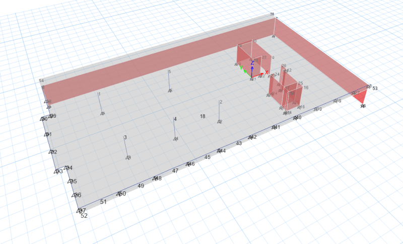
Below is the 3D view. (I have also uploaded the Etabs model above). What happened was the architect make the RHS basement walls offset a bit and back then I didn't think that was a major change so did not bother re-calculate on this until yesterday.
It is just flat slab sitting on top of capping beams, which supported by bored piers. All these lines in the pics denote capping beams (530x600(D)).
12222_fvor5e.png


Thank you for your help.
 
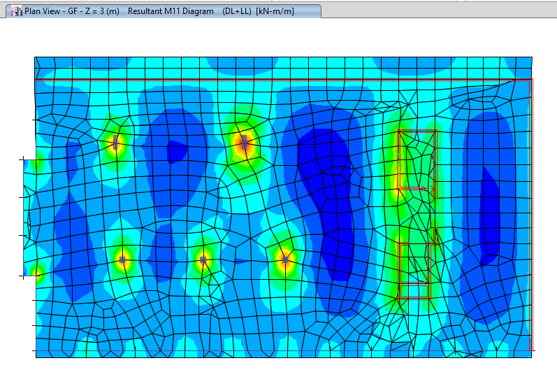
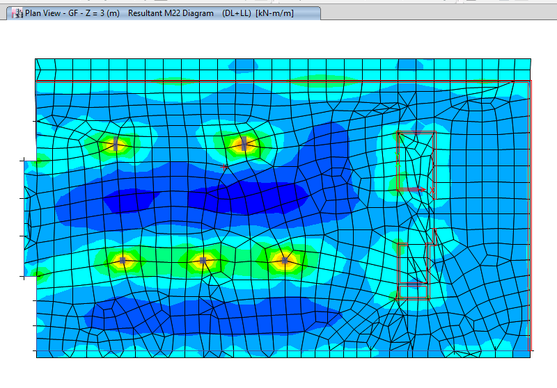
Slab is 400mm thick. I simply modelled them as rigid supports. Please find below M11 & M22 contours.
M11_ga5thp.png

m22_newtm6.png


But... I don't get why the internal slab will be cantilevered considering there are internal supports?
 
400mm thick slab, rigid supports... That creates an extremely stiff connection. Hence you get the behavior as exhibited. Naturally two rigid supports with a rigid slab will behave very stiffly compared to you other boundary conditions. Thus attracting more load.
 
400mm thick slab is because there are two more stories above and I didn't establish the full model. I just created this floor model only to see what happened.

I understand it will create a more stiff support with two close rigid restraint but what causes the uplift? I didn't expect one will be in tension and the compression in another one will increase so much though. However, this is what the actual layout is like. So which model should be adapted? The original one or the simplified straight line one? I have designed as the later one and am concerned as the results differ so much...
 
Kootk has already covered that. You have moment reversal. Or or more laymans terms a fulcrum effect on support 34 creating an uplift on 33. Think of it as a simple beam with 3 supports.
eg:

Code:
______________________
^   ^                ^
33  34               3

With a UDL you would get uplift on the far left support of labelled 33.
 

Yeah you are right. Didn't think of that. I misunderstood what KootK said as cantilever behavior.
So what happens if I had already designed them as straight lines. (KootK reckon it should be fine but I still cannot fully understand the mechanism when it was designed as simplified straight lines and then point 34 'fails'.) there are two more stories and this 'back-span' effect will be more obvious apparently and the reaction at point 34 will definitely beyond the design value I had using simplified method.
So below is my assumption: say point 34 fails in compression or deflects more (spring support?), and loads will distribute to point 33 more, which is close to my simplified straight line model? so it should be fine? What about the capping beams? if point 29/34 fails then the capping beam there will be cantilever?
 
RD2EN said:
so it should be fine?
A tentative yes. But your really should adequately look at all your assumptions. Why this is occurring and is it realistic. I say thing in general terms. In this case you loads are pretty low and I presume your piers aren't that rigid in comparison to your slab given you say that they would 'fail' at 390kN.

Supports that are significantly less stiff will deflect until an equilibrium is reached.
 
@human909: thanks for helping to explain what I was trying to convey. Nice touch with the ASCII diagram.

@RD2EN:

1) Thanks for the additional information.

2) In my opinion, you've done your due diligence with this and can now set the problem down and rest easy. You've attempted to verify your hand results with some FEM, got some quirky local effects, considered them carefully, consulted others, and have not allowed the FEM results to override your own good judgement and intuition about what is real and important here. This is textbook good engineering as far as I'm concerned.

3) It is not at all unusual for FEM runs to produce idiosyncrasies like this. FEM is great stuff but it has its limitations. As it stands, you're getting these goofy results because the model overestimates local stiffness in a bunch of different ways, probably including: cracked stiffness of the slab, axial flexibility of the piles and, most importantly, flexibility in the connection between the slab and capping beam and capping beam and piles. You didn't supply the cross section that I requested and that's fine, time is money. If you had, however, my intent was to pick that apart to demonstrate all of the sources of flexibility that such a connection would embody but which would not be reflected in your FEM model.

4) If there's a real failure mode to be concerned about here, it's probably slab punching shear failure at the re-entrant corners. And I'd not lose any sleep over that either. It's unlikely to happen and, even if it did, the slab would just crack and morph into a one way shear scenario anyhow.

5) Keep in mind that, for most of the history of structural engineering, the maximum amount of attention that this would have received would have probably been some localized top steel around the re-entrant corner. If it was good enough for your predecessors, there's good reason to believe that it will be good enough for your project.
 
Status
Not open for further replies.

Part and Inventory Search

Sponsor