Eng-Tips is the largest engineering community on the Internet

Intelligent Work Forums for Engineering Professionals

  • Congratulations waross on being selected by the Tek-Tips community for having the most helpful posts in the forums last week. Way to Go!

Detailing of a cantilever canopy 1

Status
Not open for further replies.

MSUK90

Structural
Jan 29, 2020
155
0
0
AE
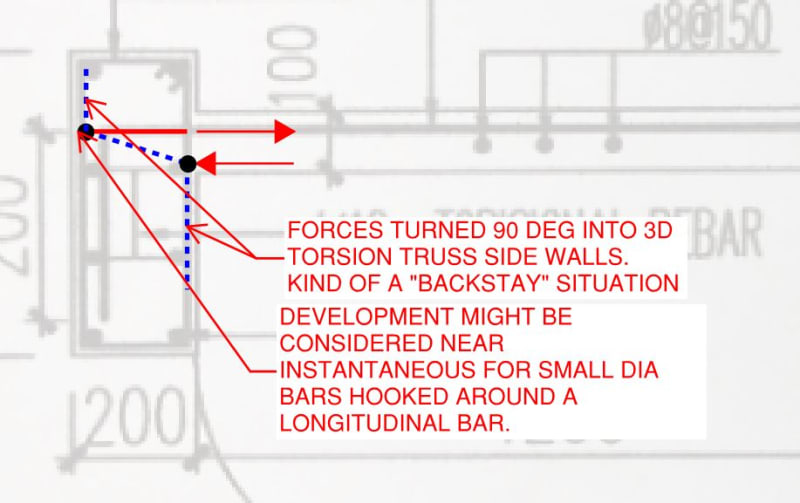
Dear Members, I came across a detail(attached in picture) for a cantilever canopy which doesn't seem okay to me. Would like to know your views about it. What I believe is that the cantilever bars should at least develop inside the beam as per the required anchorage length and beam should be sized accordingly. Alternatively, the bars can be made as loop inside the beam? Consider the beam to be designed for torsional moment developed by the slab. My issue is regarding the detail..
 
 https://files.engineering.com/getfile.aspx?folder=5a863705-e32a-4a3f-905a-319b97c4d7f4&file=IMG_7178.jpg
Replies continue below

Recommended for you

I'd imagine a 12 diameter bar will probably develop in that length via the hook. Obviously depends on the yield strength of the bar and what your code calculates out the anchorage to be from the face of the beam for a hook arrangement.

I agree with the premise that it should be developed.
 
1) Fundamentally, I agree that a developed hook here would be sufficient and practical (much more so than a loop). That said, I feel that you have three options here:

a) fully develop the slab top bars with a standard hook if the bars are being 100% utilized.

b) partially develop the slab top bars with a standard hook if the bars are less than 100% utilized.

c) use the hook tails as supplemental development length. For ACI, you'd do this as a curved bar node; in Europe, I believe it's allowed with a radius/crushing check on the bend diameter. I wouldn't do either of these things as they would add cost and complexity in the field.

2) As far as what you should do here goes, follow #1. That's practical, accepted practice in these situations and will keep you competitive relative to your competitors. That said, it is great fun to think about these details in detail and try to figure out just how flexure in the slab becomes torsion in the beam. There is more than one way to skin this particular cat but I've shown one version below which would have two interesting implications:

a) you'd need to do more than just develop the top bars within the beam as development alone would be insufficient to satisfy the strut & tie model for anchorage and;

b) you could make the case that intermediate cross ties are required as shown below in green.

Again, though, don't do this in real life. Your builder would have you strung up and, frankly, I feel that strut and tie is only marginally applicable to situations where your forces are distributed out of the page like this.

C01_qmiriv.jpg
 
I think the suggestion to hook around a bar on the far face of the beam is a very good improvement and about as good as its going to get....
 
Agent666 (Structural) said:
I'd imagine a 12 diameter bar will probably develop in that length via the hook. Obviously depends on the yield strength of the bar and what your code calculates out the anchorage to be from the face of the beam for a hook arrangement.

I agree with the premise that it should be developed.

ACI code will be used to calculate development. The bars are obviously not fully stressed.
 
KootK said:
1) Fundamentally, I agree that a developed hook here would be sufficient and practical (much more so than a loop). That said, I feel that you have three options here:

a) fully develop the slab top bars with a standard hook if the bars are being 100% utilized.

b) partially develop the slab top bars with a standard hook if the bars are less than 100% utilized.

c) use the hook tails as supplemental development length. For ACI, you'd do this as a curved bar node; in Europe, I believe it's allowed with a radius/crushing check on the bend diameter. I wouldn't do either of these things as they would add cost and complexity in the field.

2) As far as what you should do here goes, follow #1. That's practical, accepted practice in these situations and will keep you competitive relative to your competitors. That said, it is great fun to think about these details in detail and try to figure out just how flexure in the slab becomes torsion in the beam. There is more than one way to skin this particular cat but I've shown one version below which would have two interesting implications:

a) you'd need to do more than just develop the top bars within the beam as development alone would be insufficient to satisfy the strut & tie model for anchorage and;

b) you could make the case that intermediate cross ties are required as shown below in green.

Again, though, don't do this in real life. Your builder would have you strung up and, frankly, I feel that strut and tie is only marginally applicable to situations where your forces are distributed out of the page like this.

You nailed it(as always). Regarding your point 2(a)- I also believe that just developing the bars wouldn't be sufficient to make the connection fixed. Generally, there are some other ways for the moment to flow but for this type of typical scenarios where the slab has to be totally supported by beam, how can I achieve full fixity(at least to support slab through torsion) except developing the bars into beams??
I would like to know your views on it.
Thank you.
 
MSUK90 said:
I would like to know your views on it.

For this particular example, I'm confident that you will achieve sufficient joint restraint given that:

1) Closing joints, in general, tend to do quite well. At least that's the case relative to opening joints. We discussed the bejeezus out of this topic a while back here: Link

2) You'll likely have small diameter bars.

3) You have that rather wonderful clamping action that the beam up-stand will provide. See the diagram below. Many code prescribed beam to column moment joints also will not satisfy this kind of strut and tie checking. And, in those instances, the forces involved are much more concentrated. I am willing to accept that, if these joint details are good enough for the fine folks at ACI etc, they ought to be good enough for me. I would hope that the code detailing recommendations have been informed by laboratory testing which trumps all other forms of engineering knowledge but I don't know the details of that.

While I like the longitudinal bar in the hook knuckle, I'm even willing to bend on that given that it might pose a constructability issue for close stirrups. My understanding is that the improvement that such a bar would provide would be mostly related to longitudinal clamping/confinement of the hooks rather than mechanical interlock between the bars. It's hard to imagine that similar clamping wouldn't also be provided by all of the beam top and bottom bars which aren't all that far away from the hooks after all.

c01_yprw6a.jpg
 
1. For beam-slab joint, check the development length to develop yield strength. (If saving rebars is the aim, alternate mix full and half length bars)
2. Check the torsional strength of the beam, including rotation, that would resulted in larger slab deflection.
3. Improve the rebar detail for parapet-slab joint, the looped bar is an uncalled burden for fabrication, and may impact quality concrete placing.
 
retired13 said:
3. Improve the rebar detail for parapet-slab joint, the looped bar is an uncalled burden for fabrication, and may impact quality concrete placing.
Thanks for your valuable views.
Can you please elaborate your third point?
I think the other option is to just develop the bars from the parapet into the slab(like hook bent inside the slab) and end the slab bars at its edge.
 
MSUK90,

Yes, that's exactly my thought, as a L bar in the parapet is quite the norm, and simple for fabrication.
 
Status
Not open for further replies.
Back
Top