Ashenbrenner
Structural
Good afternoon engineers!
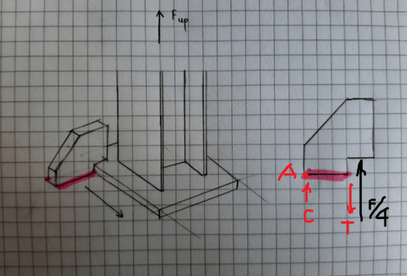
I am struggling with understanding the concept of the hand calculations for the case shown in the attachments.
In short, there is a structure which is located on sea transport. Each column of this structure has a welded to it endplate which is locked to the grillage system via the wingplates. Wingplates are welded to the transport beams (marked in red). There is an uplift force applied in the centre of each column.
My question is, what kind of approach would you use for the hand calculations, to define the thickness and dimensions of the wingplate and the weld size per plate (how to calculate stresses and deformation in the plate). In total there supposed to be 4 wingplates - 2 on each side.
Thanks in advance!

