Continue to Site

Eng-Tips is the largest engineering community on the Internet

Intelligent Work Forums for Engineering Professionals

  • Congratulations IDS on being selected by the Eng-Tips community for having the most helpful posts in the forums last week. Way to Go!

EN 50522 permissible touch voltage - body resistance question

Status
Not open for further replies.

tofulover

Electrical
Jun 17, 2020
40
Hi all,

I have searched the forum and found a few threads about the permissible touch voltage calculations but the threads do not answer my question so I would like to ask here.

I wanted to calculate the permissible touch voltage as per EN 50522 and/or IEC 60479.

Referring to annexe A of EN 50522, I can see that the permissible touch voltage is calculated using 4 weighted values. I understand that. However, how does one determine the boy resistance in each case?

So if I understand correctly, using a disconnection time of 0.05sec for instance, we need to run 4 calculations and then obtain the weighted values.

Case 1
Ib = 900mA, HF = 1.0, BF = 0.75, Weighted = 1
So Utp = Ib(tf) x 1/HF x ZT(UT) x BF
and weighted value then becomes Utp x 1

Case 2
Ib = 900mA, HF = 1.0, BF = 0.5, Weighted = 1
So Utp = Ib(tf) x 1/HF x ZT(UT) x BF
and weighted value then becomes Utp x 1

Case 3
Ib = 900mA, HF = 0.8, BF = 0.75, Weighted = 1
So Utp = Ib(tf) x 1/HF x ZT(UT) x BF
and weighted value then becomes Utp x 1

Case 4
Ib = 900mA, HF = 0.4, BF = 1.0, Weighted = 0.7
So Utp = Ib(tf) x 1/HF x ZT(UT) x BF
and weighted value then becomes Utp x 0.7

And then get the average value of the calculated Utp from above.

The question is, how do we get the body resistance ZT(UT) in the first place?

Thanks for any insight!

Cheers

 
Replies continue below

Recommended for you

Tofulover:

You must solve a non-linear circuit. You have some linear resistances (RF) plus the body resistance in series.

Rbody = Rb(V) from a table (B.2 of EN 50522).

For a time t =0.05 seconds, Ibody= 900 mA. You must apply the corrections factors for HF and BF to obtain Iadjusted.

U= (Rb(V)+RF)*Iadjusted

You must use any iterative procedure.

If RF= 0 you can calculate the four values for the different curcuits with the weigths factors, and you can obtain one point of the figure 4, or Table B.3, or the curve (1) of figure B.2

It is difficult to obtain exacts values, principally because some parameters are given as curves and not as tables.


Regards,

OPH. 2020-06-17 16:50

 
Thanks erdep. I have been thinking about what you said for the past 2 days but i still could not figure this out.

If you could please walk me through step by step:

Case 1
Ib = 900mA, HF = 1.0, BF = 0.75, Weighted = 1
Iadjusted = Ib(tf) x 1/HF x BF = 900mA x 1/1 x 0.75 = 675mA.

Zt(Ut) = Rbody + RF.
Assume RF = 0.
So Utp = Rbody x Iadjusted.

This is the part where I start to fall apart.

you say, "If RF= 0 you can calculate the four values for the different curcuits with the weigths factors, and you can obtain one point of the figure 4, or Table B.3, or the curve (1) of figure B.2"

Could you show this step-by-step? How do I get the body resistance from Table B.3 or the curve #1 of figure B.2?

Thanks


Not to be authoritative but to broaden your understanding of the factors involved in touch voltages:
The Canadian Code puts much weight on the ground conditions rather than the body resistance.
________ Tolerable touch voltages: 0.5 Second Duration
Ground conditions: ______ Ohms per meter ______ Max Touch Voltage
Wet organic soil. _____ 10 Ohms per meter ____ 166 Volts
Moist Soil ___________ 100 Ohms per meter ____ 188 Volts
Dry Soil _____________ 1000 Ohms per meter ___ 405 Volts
150 mm Crushed Stone _ 3000 Ohms per meter ___ 885 Volts _ Typical Substation
Bedrock ____________ 10,000 Ohms per meter ___ 2569 Volts

Bill
--------------------
"Why not the best?"
Jimmy Carter
 
tofulover,

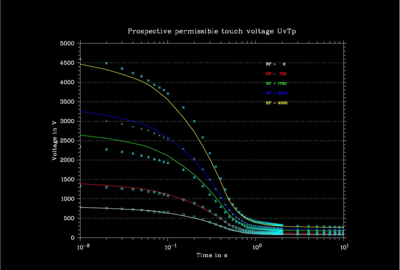
It is more easy to send the fortran code (and the executable) that calculates (or die in the intent) the curves of Fig B.2

Link

The figure I obtain:

figb2_ujpfgd.jpg


The program creates a file touchall.plo, to be processed by the program fplot.exe that I send in the same archive.

Only the Rf=0 curves are near the same as EN 50522. Part of the differences may be due to not accurate values on tables (Resistances are rounded to 25 Ohm).

If you can found a cause of errors and solve the problem, I will be happy with the information.

Regards,

OPH. 2020-06-19 06:26
 
Thanks erdep. This is very impressive.

Could you re-upload that file to dropbox? when i downloaded it says there is packed file error.

Could you also do a hand calculations step by step how do you get the resistance values for the Rf=0 curve?

Thanks!
 
Tofulover

No, it is not a simple job to do it manually.

The simplest method is the bisection:

Link

But in this case you have not a closed function to calculate.

You have one (or more) tables with few values.

You must found a value in a table, and the best is to use interpolation.

But linear interpolation is not too good for tables as that we have, the best is to use a log-log interpolation, and a better method that linear.

The best I found is the so called "shape preserver"

By all this reason I added all in a Fortran program.

Regards,

OPH. 2020-06-19 11:57
 
Thanks erdep for all the info you posted. I will have a closer look at the bisection method.

But what I wish to ascertain at this stage is the "Concept" of this touch voltage first. Could you please see my concept below is correct.

To produce a graph similar to Figure 4, EN 50522, we do the following:

Let's assume we use a 50% percentile.

Step 1: From Table B.2, convert the body impedance which is "hand to hand" to "hand to feet" by multiplying by 0.75. and then divide the touch voltage by the hand to feet body resistance:

Vt - Zt(HtoH)- Zt (HtoF)- Ib
25V - 3250 ohm - 2438 ohm - 11mA
50V - 2500 ohm - 1875 ohm - 27mA
75V - 2000 ohm - 1500 ohm - 50mA
100V - 1725 ohm - 1294 ohm - 78mA
125V - 1550 ohm - 1163 ohm - 108mA
150V - 1400 ohm - 1050 ohm - 143mA
175V - 1325 ohm - 994 ohm - 177mA
200V - 1275 ohm - 957 ohm - 209mA
225V - 1225 ohm - 919 ohm - 245mA
400V - 950 ohm - 713 ohm - 562mA
500V - 850 ohm - 638 ohm - 784mA
700V - 775 ohm - 582 ohm - 1203mA
1000V - 775 ohm - 582 ohm - 1719mA

and then using the above calculated body current, refer C2 curve and obtain the duration of current flow.

11mA - 10sec
27mA - 10sec
50mA - 5sec
78mA - 1sec
108mA - 0.8sec
143mA - 0.63sec
177mA - 0.54sec
210mA - 0.51sec
245mA - 0.48sec
562mA - 0.23sec
785mA - 0.13sec

and then use the above values to plot the curve similar to Figure 4 of EN 50522.
We can repeat the above for the 5% percentile, 95% percentile, and C1 and C3 curves.

Is my concept above correct?

Appreciate if you could enlighten me.

Thanks again


Tofulover

Yes, it is correct.
To complete the work you must calculate four tables as you did, with the corresponding HF and BF, and calculate the weighted average to obtain the table B.3 (or the curve of figure 4).

The curves of figure B.2 require the addition of RF for each case.

You end with tables of Time(Ibody), but I needed the reverse: a table with Ibody(time), for times as the ground system owner use to verify it. It is not a hard work.

Furthermore, por each point in the surface of the terrain, a Potential is calculated by any software for ground design.

The Touch Voltage as IEEE Standars define is Vtouch=GPR-Potential, and Ibody= Vtouch/(Rbody+RF), Rbody = 1000 Ohm. It is a easy work.

But for EN50522, Vtouch=GPR-Potential, but Ibody requires to solve the non-linear circuit Vtouch=Ibody*RF+Ibody*Rbody(Vbody), for all the area of interest.

Erdep programs solve this circuit for any of the four cases of EN50522, but one at the time.

It calculates the admissible Touch Voltage(time) for the four cases:


EN 50522
--------
CIRCUIT LEFT HAND-BOTH FOOT
CORRECTION FACTORS
CONTACT HEART CURRENT FACTOR 1.00000
CONTACT BODY RESISTANCE FACTOR 0.75000

STEP HEART CURRENT FACTOR 0.04000
STEP BODY RESISTANCE FACTOR 1.00000

PERMISSIBLE ACCIDENTAL BODY CURRENT (mA) 76.00000
PERMISSIBLE ACCIDENTAL TOUCH CURRENT (mA) 76.00000
PERMISSIBLE ACCIDENTAL STEP CURRENT (mA) 1900.00000

BODY TOUCH RESISTANCE (Ohm) 1734.69965
ADJUSTED BODY TOUCH RESISTANCE (Ohm) 1301.02474
BODY STEP RESISTANCE (Ohm) 775.00000
ADJUSTED BODY STEP RESISTANCE (Ohm) 775.00000
ADDITIONAL TOUCH RESISTANCE RF1 (Ohm) 0.00000
ADDITIONAL TOUCH RESISTANCE RF2 (Ohm) 15.00000
TOTAL ADDITIONAL TOUCH RESISTANCE RA (Ohm) 15.00000
TOTAL TOUCH CIRCUIT RESISTANCE (Ohm) 1316.02474
ADDITIONAL STEP RESISTANCE RF1 (Ohm) 0.00000
ADDITIONAL STEP RESISTANCE RF2 (Ohm) 60.00000
TOTAL ADDITIONAL STEP RESISTANCE RF (Ohm) 60.00000
TOTAL STEP CIRCUIT RESISTANCE (Ohm) 835.00000
PERMISSIBLE BODY VOLTAGES
TOUCH VOLTAGE (V) 98.87788
STEP VOLTAGE (V) 1472.50000
PERMISSIBLE VOLTAGES
TOUCH VOLTAGE (V) 100.01788
STEP VOLTAGE (V) 1586.50000


CIRCUIT HF BF WEIGHT VTP
LEFT HAND-BOTH FOOT 1.00 0.75 1.00 100.02
RIGTH HAND-BOTH FOOT 0.80 0.75 1.00 116.47
BOTH HANDS-BOTH FEET 1.00 0.50 1.00 76.79
RIGTH HAND-LEFT HAND 0.40 1.00 0.70 230.56
RIGTH FOOT-LEFT FOOT 0.04 1.00 0.00 1586.50
WEIGHTED AVERAGE 113.67
ACCORDING TO EN50522 117.54

The step voltage RIGTH FOOT-LEFT FOOT is not added to the average (WEIGHT=0), only IEEE Guide 80 requires this voltage.

Regards,

OPH. 2020-06-20 06:35


Thanks Erdep. It is good to know I am on the right track.

You mentioned this: "To complete the work you must calculate four tables as you did, with the corresponding HF and BF, and calculate the weighted average to obtain the table B.3 (or the curve of figure 4)".

How do I incorporate the HF and Weighted value into my steps above?
Utp is calculated as Ib(tf) x 1/HF x ZT(UT) x BF but in my steps above, the Utp is not a calculated value but still based on the table, i,e. 25V, 50V, 75, 100V, 125V, etc.

Another question is: How do I get the table with the function Ib(time) using my steps?
 
Tofulover

Your procedure solves the problem for one of the four circuits each time.

BF is a factor to modify Rbody to take into account the real circuit
HF is a factor to take into account the true current by the heart

Look Annex A of EN50522

Vt - Zt(HtoH)- Zt (HtoF)- Ib
25V - 3250 ohm - 2438 ohm - 11mA
50V - 2500 ohm - 1875 ohm - 27mA

In your sample, Rcorrected= 3250*BF = 3250*0.75= 2438 (you did this part)
For rigth hand to both foot: HF=0.80
Icorrected=11/0.80= 13.75 mA

If you need only this circuit, it is OK. If your need the four circuits, use the HF and BF and calculate the current for each circuit.

[tt]
CIRCUIT HF BF WEIGHT VTP
LEFT HAND-BOTH FOOT 1.00 0.75 1.00 100.02
RIGTH HAND-BOTH FOOT 0.80 0.75 1.00 116.47
BOTH HANDS-BOTH FEET 1.00 0.50 1.00 76.79
RIGTH HAND-LEFT HAND 0.40 1.00 0.70 230.56
WEIGHTED AVERAGE 113.67
ACCORDING TO EN50522 117.54


[/tt]

With this, you can calculate four values of current, but, what to do with this values?

You need four values of voltage to calculate average, not the currents. The non-linear Rbody is the root of the problem.

It is the reason I solve the non-linear circuits for each case (the hard way). Well, not too hard to be solved by a program.

Regards,

OPH. 2020-06-20 07:46


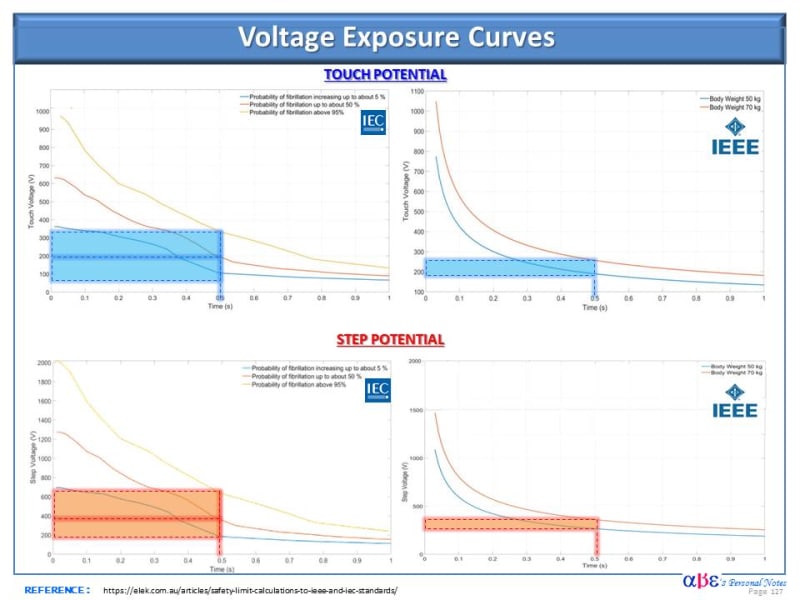
Here are generic plots for step & touch voltage exposure curves per IEC & IEEE Standard.

I hope this helps to loop in the ANSI engineers in this discussion.

Voltage_Exposure_for_Step_Touch_Pot_per_IEC_IEEE_Stds_qzlwa2.jpg
 
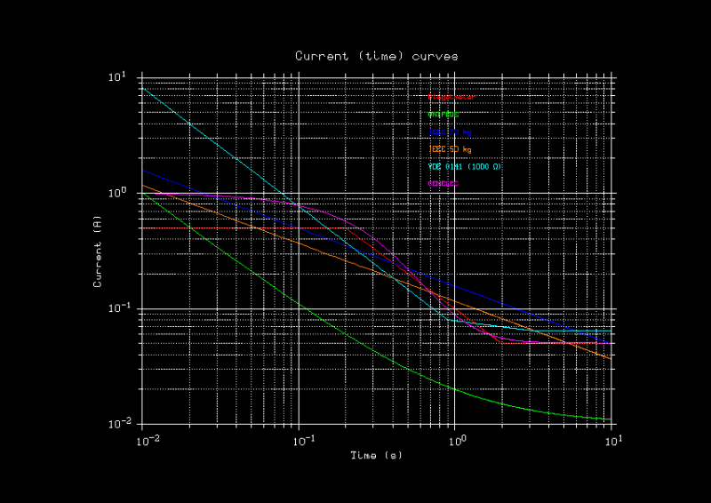
All the Standards define Current as the variable that can produce risk, and finally all define tables or curves of Voltage.

Look the Current(time) for different Standards (or author in one case), some obsolete.

Depending of how the Standard define Rbody the calculation will be easy (IEEE 80, VDE 0101) or difficult (as EN50522-IEC60479-CENELEC).

etodos01_zvotqp.png


A wide range or variation.

Regards,

OPH. 2020-06-20 18:04
 
Hi Erdep,

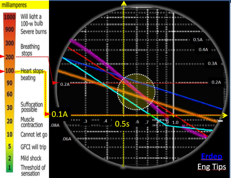
Thanks for sharing with us the max. allowable shock current per different standard.

Allow us to take the liberty of using your graph and see that most of the standards provide comparable values of allowable shock current for typical clearing time ranging from 0.3s to 0.4s.

I recalled seeing similar thoughts in an IEEE paper that compared various standards.

>>>>>>
Allowable_Shock_Current_per_Different_Stds_yp3azj.jpg
 
Hi Erdep,

Thanks for your comments so far.

You said:
"With this, you can calculate four values of current, but, what to do with this values?
You need four values of voltage to calculate average, not the currents. The non-linear Rbody is the root of the problem.
It is the reason I solve the non-linear circuits for each case (the hard way). Well, not too hard to be solved by a program."

I agree with you. Having 4 values of the current is not useful and the issue is the non-linear Rbody. Let me just try to understand. The shape preserver curve that you program using Fortran is to based on which curve? Is it trying to obtain the curve from Table B.2 of EN 50522?

I am no good with Fortran so would like to approach this using Microsoft Excel instead. You mentioned a log|log graph which is a great idea. For Table B.3, can I not log the Touch voltage and then log the body impedance and then use this to provide a linear relationship?


Tofulover

When you have not a function to calculate a value from some argument, and you have a table, you can interpolate using the table.

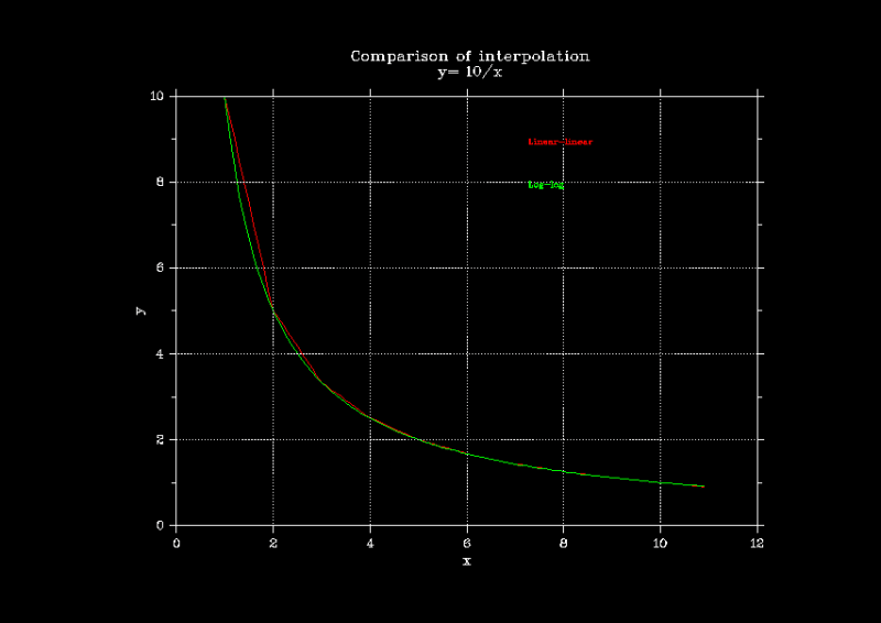
If you have few values in the table, the linear interpolation may work well for some cases, but if yoy want a log-log plot, you will see not rectilinear segments (proper of linear interpolation), yo will see curves with reverse form as required, as arcs of rope.

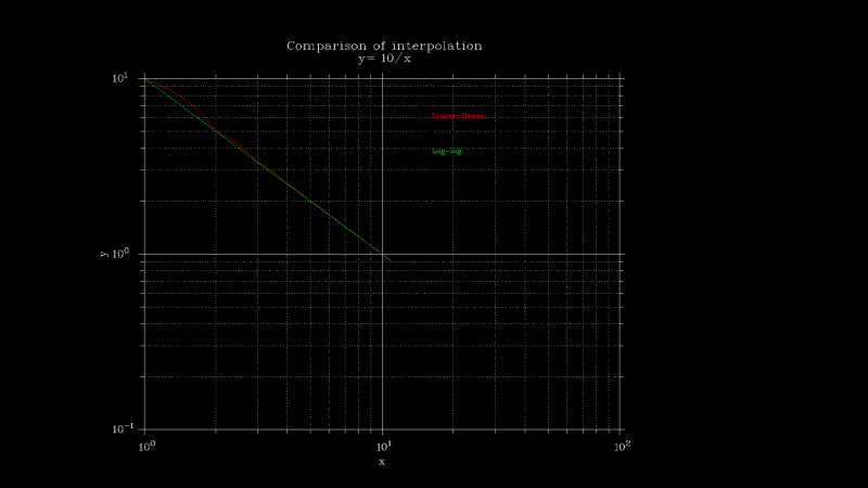
Interpolating with log(x) and log(y) and reversing the values by 10**(log(y)), the shape of the curves are better respected. Using a preserving shape interpolation, the result are the best.

I am not user of Excel, but surely the interpolation can be done with it. The log-log interpolation may be sufficient despite the interpolation is linear.

The procedure is to use x --> log(x)-->log(y)--> 10**y

Regards,

OPH. 2020-06-21 15:21

 
Tofulover

To be sure about the problem of lin-lin itnetrpolation I was clear, I prepared two figures. A table of ten values of x (1...10), y=10/x.
In both cases the interpolation was done linearly, from x=1 to 10 in 0.1 steps, but the second figure was calculated with
the procedure x--> log10(x)--interpolate--with a log-log table, and recover the interpolated value by y=10**y

The interpolation is linear in both cases, surely it is simple in Excel.

L01_om11mm.png


L02_i8tevx.png


Regards,
 
Hi Erdep,

I have now done this in Excel - a log(Zb) vs log(Ib) curve.

Edit: not sure why the image cannot be uploaded but here is the link.

Link

From the curve, a trend line is also automatically produced by Excel with the equation as noted.

What do you think of this approach for the determination of Zbody? I know the curve preserving interpolation is the best but would my method above be also functional?

Thanks
 
Status
Not open for further replies.

Part and Inventory Search

Sponsor