Eng-Tips is the largest engineering community on the Internet

Intelligent Work Forums for Engineering Professionals

  • Congratulations waross on being selected by the Tek-Tips community for having the most helpful posts in the forums last week. Way to Go!

A minimum material envelope as a datum feature simulator 1

Status
Not open for further replies.

Burunduk

Mechanical
May 2, 2019
2,335
0
0
IL
I noticed that para. 4.5.1 in Y14.5-2009 lists "(d) a minimum material envelope" as an example of a datum feature simulator. How is this specified on the drawing and what kind of applications is it useful for?
I thought that for datum features referenced RMB, the UAME (in case of primary) or RAME (in case of secondary/tertiary) is the datum feature simulator. For datum features referenced with material boundary modifiers, the simulator is the MMB or LMB boundary. Never have I seen how and when a UAMME/RAMME datum feature simulator is invoked...
 
Replies continue below

Recommended for you

Burunduk,

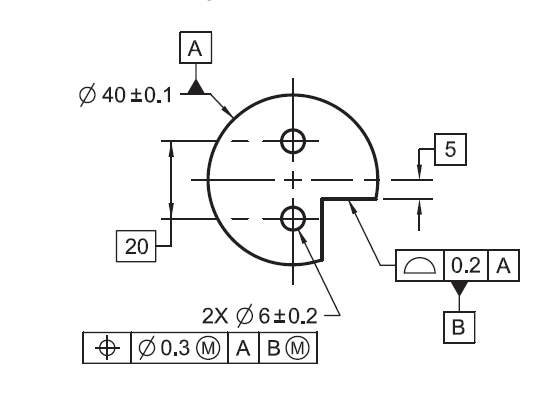
With the 2009 version, MMB or LMB can be applied to any feature. The feature does not have to be a feature of size. However, it has to make sense. For instance, you can't have 3 perpendicular planar features and call them out as MMB or LMB. The feature should have a fixed boundary, rather than a floating boundary.

1_y3fjd6.png


Instead of A|B(M}, you can have A|B(L)... Since MME (whether unrelated or related) is always inside the material, you can't have a physical gauge to simulate it. I use LMC quite a lot for locating purposes. However, I have never seen any callout with LMB on datum features.

Even in ASME Y14.8-2009 "Castings, Forgings, and Molded Parts" standard I couldn't see any example. I would assume using LMB would be somehow related to conserving the minimum material. It wouldn't be a physical Datum Shift, but maybe an "imaginary shift" to allow you to accept more parts, based on the calculation, similar to MMB Datum Shift calculation.
 
Hi Burunduk,

This same mistake is in both the 2009 and 2018 versions of Y14.5. There is no way to specify an unrelated actual minimum material envelope as a TGC.

I believe Bill Tandler has been saying for at least 10 years now that there should be a way to do this. His way of saying it is to call our default RMB case, for which the unrelated actual mating envelope is the TGC "S+" and the case for which the unrelated actual minimum material envelope would be the TGC "S-". I also believe that he extends the concept to lower precedence datum features, with his "Tandlernology" being that the orientation constrained actual minimum material (I think he actually says "in-material") envelope, or the location constrained actual minimum material enveloped can be a TGC (he would say datum feature simulator) also, depending upon the relationship to higher precedence datum features.

If we do need this new method added to Y14.5 I'll be interested to see discussion about functional needs that would drive this choice. A centering/tight fit relationship with the mating assembly which is best modeled with the low points of the feature when the high points will be sheared off in assembly or worn off early in life possibly?

Dean
 
Dean, thanks for this very interesting information. So does Bill Tandler suggest to show the "S+" or "S-" symbol as a material boundary modifier in the FCF, similar to the way the circled M or L for MMB/LMB?

No wonder he comes up with original uses for the old S modifier, it seems to be one of his favorites.
I remember reading not long ago an old ASME Y14.5M-1994 based article by him where he recommended using the circled S modifier for RFS, even though per the 94' standard RFS was already the default when no modifier is shown (but the modifier was still allowed).
 
Tarator, |A|B(L)| does not invoke a minimum material envelope datum feature simulator, but a least material boundary datum feature simulator.
 
Dean Watts said:
This same mistake is in both the 2009 and 2018 versions of Y14.5. There is no way to specify an unrelated actual minimum material envelope as a TGC.

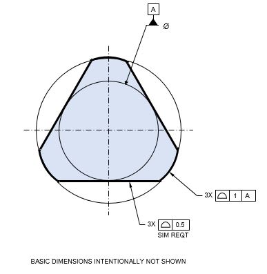
How about something like this?

capture_1_xgwwwl.jpg
 
Burunduk said:
Tarator, |A|B(L)| does not invoke a minimum material envelope datum feature simulator, but a least material boundary datum feature simulator.

Not in the example I gave, but if B was a feature of size, then it would invoke a MME, wouldn't it?
 
pmarc,
Doesn't the 0.5 profile tolerance on the form, mutual location and orientation of the three flats allow them to be either 0.25 inside the diameter of datum feature A, 0.25 outside of it, or anywhere in between? If yes, how is A a minimum material envelope?

Tarator said:
Not in the example I gave, but if B was a feature of size, then it would invoke a MME, wouldn't it?

No, it would also invoke the least material boundary as the datum feature simulator.
 
Burunduk,

I think I see where your question is coming from. Other than mentioned in 4.5.1(d), there is really no such thing as "Minimum material envelope" in Y14.5-2009, therefore I took it as "Actual minimum material envelope", which is in line with what 4.5.1(d) evolved into in corresponding para. 7.5.1 in 2018:
"(e) a related actual minimum material envelope
(f) an unrelated actual minimum material envelope".
 
pmarc,
I too understand the 4.5.1(d) "minimum material envelope" to mean either unrelated or related minimum material envelope. The lack of "unrelated"/"related" in the wording is not what triggered my question. It is more about how such datum feature simulator/true geometric counterpart should be invoked in the drawing.

As for your example, I think I see how this suggests the minimum material envelope as a datum feature simulator, but I have two questions regarding it:
First, how do we know that the inscribed theoretical cylinder is just inscribed in the actual feature and not part of the basic geometry definition (I.e. fixed in size and not necessarily tangent to the flats on the low points). In cases such as fig. 4-35 in the 2009 standard I would expect the three pins pattern to be fully defined with basic dimensions and position tolerance, then the circumcircle with no diameter value is clearly adjustable at size to contact the surface of the as-produced pins. With the profile application as shown in your example - I'm not sure the same interpretation is expected.
Secondly, why is this cylinder the actual minimum material envelope rather than three theoretical planes that contact the low points on the flats?
 
Burunduk said:
First, how do we know that the inscribed theoretical cylinder is just inscribed in the actual feature and not part of the basic geometry definition (I.e. fixed in size and not necessarily tangent to the flats on the low points). In cases such as fig. 4-35 in the 2009 standard I would expect the three pins pattern to be fully defined with basic dimensions and position tolerance, then the circumcircle with no diameter value is clearly adjustable at size to contact the surface of the as-produced pins. With the profile application as shown in your example - I'm not sure the same interpretation is expected.

I am not sure why the same interpretation could not be expected here. The dimension for the diameter of the circle/cylinder has no value, just like in fig. 4-35/2009. The profile tolerance for the flats controls relationship between them just like position tolerance would control relationship between the three pins. Additionally, the cylinder A cannot be considered fixed in size because it has been referenced RMB in the profile callout, not LMB or BSC.

Burunduk said:
Secondly, why is this cylinder the actual minimum material envelope rather than three theoretical planes that contact the low points on the flats?
They (the three planes) could be, but because I specifically made the cylinder the considered feature, the actual minimum material envelope is cylindrical. Again, the logic is similar to what we see in fig. 4-35.
 
pmarc, thank you for clarifying. I now clearly see the similarity to the concept shown in fig. 4-35 (only with the relevant envelope being "inside the material") and I agree that this is a possible case of what should be interpreted as a minimum material envelope datum feature simulator.
 
pmarc and Burunduk,

I believe that the examples shown in Fig 4-35 of Y14.5-2009 and pmarc's example above all depict mating envelopes instead of minimum material envelopes. To make any of these into examples of using the "actual minimum material envelope" to establish a datum, I think a note is needed to explicitly state the the envelope must be fit to the low points.

What am I missing?

Another point that I think would be interesting to talk about is why "SIM REQT" is added to the profile applied to the 3 planar surfaces in pmarc's example. If we don't need that note when profile is controlling coplanarity or "co-stepularity", then why do we need it in this case? Yes, I'm picking on the lack of sufficient grouping rules that we all know are on their way to be improved, but I would like to learn what difference you see as making SIM REQT necessary here. Just the lack of an example figure in Y14.5 for this particular application? What if I said that SIM REQT is never needed for profile, since the concept is that it controls coplanarity and stepped parallel planar surfaces without this note, so it will control the relationship between the features that are not parallel without the note as well? What about profile all around, which I believe is controlling all features connected and seen edge-on in the particular view and the relationship between them, with no SIM REQT added?

Dean
 
Dean,

You are right that a note would make it explicit and that SIM REQT is not really needed. It still doesn't change the fact that there is a way "to specify an unrelated actual minimum material envelope as a TGC".
 
Dean,

I didn't understand pmarc's figure at first either. But now I see that the inscribed cylinder representing the irregular FOS for datum feature A is inside the material. This is different than any of the examples in Fig. 4-35, which are all outside the material.

Regarding the SIM REQTS annotation, I'm not sure about that either. The 3X would act as a grouping mechanism.

Evan Janeshewski

Axymetrix Quality Engineering Inc.
 
Evan,

What tells us whether that circle is fit as "mating" or "minimum material" in the only 3 places it interacts with the feature? I still think a note is needed to overrule the default (an the only supported) Y14.5 method of fitting to the high points of the feature.

pmarc,

If the method is to add a note, is that really supported by Y14.5, or instead requiring a note, because it is not supported by Y14.5? I think it would be good to add an explicit method that invokes the actual minimum material envelope as a TGC when that is needed.

Dean
 
Dean,
I did not say the method was to add a note. I said that addition of a note would help to clarify the intent. I still think that the circle on my drawing illustrates UAMME.
 
Status
Not open for further replies.
Back
Top