Eng-Tips is the largest engineering community on the Internet

Intelligent Work Forums for Engineering Professionals

  • Congratulations waross on being selected by the Eng-Tips community for having the most helpful posts in the forums last week. Way to Go!

Design a step footing to avoid underpinning

Status
Not open for further replies.

TimeToPlay

Structural
Jun 30, 2020
7
US
Hi all,

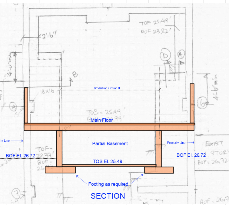
This is new 4 story high concrete building with an existing structure on the west side and an existing 1 and 2 story building on the right side. There is a 2" gap between this new building and the existing adjacent buildings.

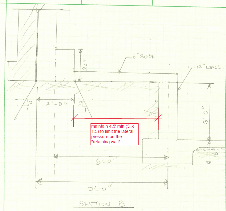
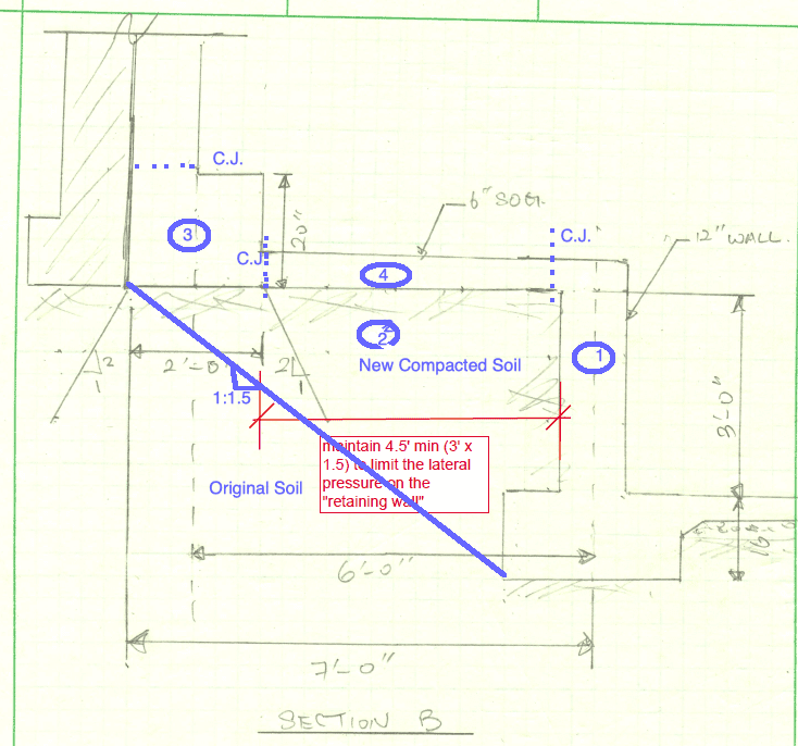
To avoid underpinning the neigbors's footing, the owner is willing to install the new footing at the same elevation as the adjacent existing footings and partial give up some of the interior space. However, there is a catch. The owner wants to maintain a desirable headroom around the center of the cellar. Therefore, I have came up with a "step" footing design to address the owner's need. Please see attached rough sketch showing the plan and sections.

I am not too sure if this design will "work".
So my questions for all of you are:
1) I am curious if anyone has designed something similar to avoid underpinning.
2) I am assuming the 20" deep footings bear on the concrete and soil below. Then the bearing stress on the concrete will transfer to the soil below.
3) Does my proposed design work without disturbing the adj footings? This detail maintains a 1V:1.5H slope.

Any suggestion is appreicated.

Thank you!
 
 https://files.engineering.com/getfile.aspx?folder=a12c0940-bb00-45b8-8fc3-aab5b63a982d&file=question.pdf
Replies continue below

Recommended for you

I think this is a renovative design. However, I might consider sheet piling if space available and been cost effective.
 
I have seen something similar, but not for a four story building. It will be difficult to support load bearing walls on footings with such high eccentricity. Offset piles might be worth considering, but we don't know what type of soil exists at the site.

It may be possible to leave the neighbour's footing undisturbed by using columns and footings far enough away from the property line that the existing foundation won't be affected, in other words, a dugout area with sufficient headroom to satisfy your client. The space between the dugout wall and the property line could be unexcavated.

Another issue which may arise is the change in snow load on the existing buildings on each side as a result of your much taller building. Who pays for the strengthening of the neighbour's roof?

BA
 
The idea of vertical load bearing onto an inclined soil slope does not sit well with me at all.

I’m not sure I’d even consider this for a single storey domestic extension let alone a 4 storey building..
 

Thanks for you advise.


To reduce the eccentricity in the footing, I am thinking to reduce the width of the footing to the actual width I needed for the design (I.e. 2'-6" instead of 5'-8" shown on the sketch) ;and separate the pour of the acutal footing and the concrete beneath it so that the footing bears on the concrete and soil.

As for the increase in snow load on the adajcent building roof, frankly, i did not consider that. Thanks for pointing that out.
 
TimeToPlay - I agree with MIStructE IRE, don't slope parts of the bottom of the footings. The detail looks "nice" on paper but is a unnecessarily expensive to construct:

Precision excavation is required.
Rebar is unnecessarily complex.
Placing rebar on a steep slope (maintaining the required 3" concrete cover between soil and rebar) is tricky.

Just use flat-bottomed stepped footings, located and sized as needed.

Note: If the argument that sloped footings "save concrete" is raised... forget it. Extra concrete is "cheap", the cost of excess construction labor will dwarf any "savings" on concrete.

[idea]
 
It is my understanding that the slopped cut is to avoid disturbing the soil under neighboring foundation. It posses a little inconvenience, but not necessary difficult to construct. Any thought from the geotechnical engineering point of view?
 
TimeToPlaY,
Check IBC code chapt 18 requires maximum footing bottom slope not to exceed 10%. [pre][/pre]
 
mfrad,

I don't think IBC 1809.3 (Stepped Footing) is applicable to this case. It is more or less for an independent footing, or a system of footing elements on slopped ground, and concerning sliding stability, which does not posses a major problem for the proposed mat-like foundation.
 
retired13,
detail on sheet 3 shows only 6 inch slab on ground which will have a isolation joint at perimeter. The sketch calls it a footing. It may rotate due to eccentric wall load. It's up to OP to determine code requirements that are applicable. I am only bringing this to his attention.
 
How will the Main Floor be framed? It could have a bearing on the design of the foundations.

BA
 
TimeToPlay:
You show pilasters or columns every so often in the side walls. Play with tighter spacing of these and then put tie beams across the bldg. and btwn. the two columns across from each other. These tie beams are down below the finished slab but tied into it so the entire bsmt. slab acts like something of a waffle mat in taking the eccentric loading from the side walls. The side walls should also be treated at deep beams spanning btwn. the tie beam systems. This is a complicated enough found. situation that I would want a GeoTech guy/gal helping me. I wouldn’t trust just kickin a little dirt to determine soil properties, and determining what I’m going to do. I would narrow your eccentric wall ftg., with its bot. elev. matching the existing ftgs., but then dig at each tie beam as close to the existing as possible, for a short construction duration, so I can tie the col., eccentric wall ftg. and tie beam all together. The mat then acts like a beam on an elastic foundation with two large line loads at its extreme ends.
 
I was thinking of something like I've shown below:

image_y7yjxp.png


BA
 
TimeToPlay,

On your original concept, make sure the base slab can resist the combined thrust and uplift pressure from the soil. Weather can be the worst enemy if the pit remains open for too long. Temporary horizontal bracing between the neighboring buildings should be considered.
 

Thanks for pointing this out. I will check the code for guidance.
 

This is a greater idea. The only trouble I have is that the shearwalls are also located at the side walls and are prutruding inside the building, applying this will make "discontinue" the shearwalls.
 

I revisited this idea and came up with the following detail.

This seems more feasible and avoids the slope footing at some of the column/foundation wall locations, although not at the shearwall locations.

My questions is....what is the ideal distance between the "upper footing" and the "retaining wall footing" so that the lower footing would not undermine the "upper footing" and also limit the amount of lateral stress on the "retaining wall". My rule of thumb is 1.5 x the change in elevation. In this case, the minimum distance beween the footings is 1.5 x 3' = 4.5' min.


Capture_uweyga.png
 
TimeToPlay,
I think going back to installing 5-ft deep underpinning piers is the way to go. You have a four story load bearing on soil that is also supporting the two-sty existing building. The new 4 story load and cellar wall load will most likely cause settlement damage to the existing adjacent foundation that you will be responsible for and should avoid. Excavating to the bottom of footing alone may cause settlement because you are removing the soil overburden. ( A geotechnical can help on evaluating this condition since we don't know the soil parameters.)

Your new sketch does not show the sequence of concrete pours which must be indicated on the drawings. If you do install the retaining wall first (as a better installation sequence) your soil berm slope is 4.33V:6.00H approximately 1:1.5 to temporarily resist lateral soil movement below the two story structure but may not be adequate enough to prevent lateral movement of the existing structure. Check with your geotechnical on whether soil can be cut on the steep 2v:1h slope that you show.

 
TimeToPlay,

Your latest sketch shows a dimension of 3'-0" between bottom of existing footing and top of new slab. Initially, you show BOF 26.72 and TOS 25.49, a difference of only 1.23' (say 1'-3"). Was I misinterpreting your elevations?

If a specified headroom is required in the basement, then the depth of Main Floor beams may have to be limited, so perhaps it is too early to establish the elevation of basement floor.

BA
 
Status
Not open for further replies.

Part and Inventory Search

Sponsor

Back
Top