Eng-Tips is the largest engineering community on the Internet

Intelligent Work Forums for Engineering Professionals

  • Congratulations waross on being selected by the Tek-Tips community for having the most helpful posts in the forums last week. Way to Go!

Free Body for Pump Nozzle and Pump Bracing Forces/Moments 1

Status
Not open for further replies.

abot93

Mechanical
May 21, 2020
10
0
0
US
Good morning all,

I have completed the stress analysis on two vertical turbine pumps and have gotten my nozzle loads. The vendor wants to put a brace on the back of the pump that will be connected to a nearby steel beam. I'm trying to work out the correct loads on this brace from the resulting nozzle loads and wanted to see if I was thinking about it correctly. This doesn't really feel right to me, so I was hoping someone might be able to point me in the right direction if this is completely wrong.
Pump_Free_Body_sy8spu.jpg


Thanks in advance
 
Replies continue below

Recommended for you

Hi

What’s the pump mounting flange fastened onto? Why does the vendor want to put a race on the pump, it would of thought the pump mounting flange was sufficient.
Is there some resultant force acting that the race needs to cancel out?

“Do not worry about your problems with mathematics, I assure you mine are far greater.” Albert Einstein
 
Thanks for the response @desertfox,

The pump mounting flange is fastened to an approx. 2500 lb pit cover as shown below.
Pump_Mounting_Plate_ecwwfl.jpg

The pit cover itself is resting on concrete that is part of a raw water intake structure extending out into the river.

As to why they wanted to install the brace, I am not able to speak with the manufacturer directly unfortunately so I can't say at the moment. We received word through our local vendor of the manufacturer's design decision, but here's some additional information that may provide some insight.

With the below grade vertical discharge pumps, the allowable nozzles loads are very low due to the geometry of the pump and the distance of the nozzle from the mounting flange with an additional "unity" requirement.
Below_Grade_discharge_loads_ymb5en.jpg

Required_Methodology_anpqnx.jpg


We have an asymmetrical layout, 30" STD pipe with 40 degree temp. variation, expansion joints, and it's an existing structure where I could not be provided accurate stiffness values during my pipe stress. I imagine my forces are conservative, but I couldn't justify reducing the support stiffness values any lower than where I had them. That's all to say that we're reporting sizeable forces and moments on a pump that has low allowables.

We requested API Double Load Nozzles, and they have beefed up the pumps, part of which includes these braces. The existing pumps have similar braces in the same location as well for what it's worth when they did the design 40 years ago.

"Is there some resultant force acting that the (b)race needs to cancel out?"
I would guess they are trying to minimize displacement/strain from the axial nozzle loads impacting the bearings/couplings, but again, I don't have access to the manufacturer so I can't say with certainty why they have the brace.
 
I would guess the "brace" may be installed to correct a vibration problem. If that is the case, then you might want to evaluate dynamic forces and not just static loads.

Walt
 
What you have looks fine except you're going to have the loads shared by the pump mounting plate and the bracing. You don't want an over-constrained system that bends the pump housing. You might consider shimming at assembly.
 
Hi abot93

Once you put the brace in I think the structure becomes more difficult to analyse because you have a mounting plate and a brace both of which will absorb load depending on there relative stiffness, in other words a statically indeterminate structure. However if you install the brace in accordance with the vendors instruction I can’t see you need to worry, unless the external loads you have calculated are in excess of the allowable flange loads or you are just unsure.
What the nozzle loads from your analysis and how do they compare with the allowable?

“Do not worry about your problems with mathematics, I assure you mine are far greater.” Albert Einstein
 
I'd bet any item off the dollar menu that the honorable Mr Strong is correct.

The 2500 lb, 2 " thick pit cover covering a (scaled) 3.5 foot opening looks more like a trampoline or cookie sheet to me.
In my opinion the grouting and anchor bolt shimming and base leveling as-built details may very possibly NOT be what is shown on the drawing,
And by themselves cause excessive vibration that can start an expensive and adversarial side trip for the project.
Note the pump stool is perforated with two , and maybe even 4 nice big access windows. A fine thoughtful feature for installation and maintenance.
But as far as providing much stiffness in bending and to a lesser degree in torsion, [bat][snake] .
Fast forward to commissioning, and then refer to Prajesh Mistry's recent post in the Mechanical Acoustics/Vibration engineering forum.

I'd personally be interested in details of "the brace" and testimonials/ success stories of it's effectiveness.
Is the brace part of the original installation instructions, or did it show up in a recent 11th hour factory bulletin?
I believe this is another example when the big picture including history and back stories is required before undertaking an analysis.
The devil is definitely in the boundary conditions.
 
I have seen several smart analytical modelers brought to their knees by boundary conditions for dynamic forces and the resulting vibrations! Tip of the hat to Tmoose!

Walt
 
Is this a new installation?

If the pump nozzle has a flange for a bolted connection.

Why would you need an extra brace?

In my opinion you should:

Double check minimum submergence over the eye of the suction impeller.

Probably should recheck your base plate thickness as well.


Maybe a little off topic..

I have done a few pontoon designs for VTP pumps as presented in the images.

Not sure of the specifications of the pump you are using, but there is an initial uplift force that you may need to consider. This force was not specified on any GA's however through discussions with the design office for the pump this information was uncovered.
 
Good morning All,

Sorry for the delayed response, I've been away from my laptop for the better part of a week now.

Some updates on these pumps:
[ul]
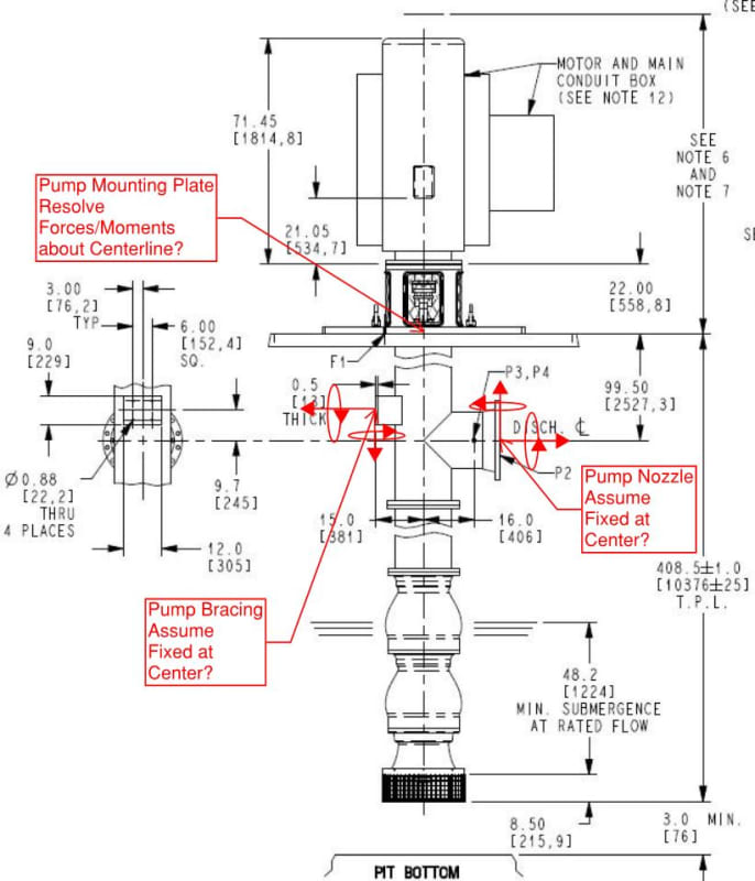
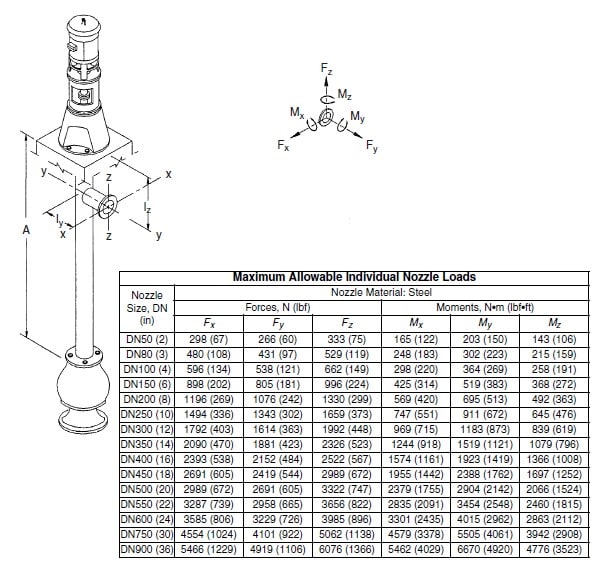
[li]Most design aspects of this pump, including the base plate, pump stool, brace, etc., are being designed by the manufacturer. Our company is not specifying these design choices, basically just approving the pump curves and dimensions to ensure it fits up to the piping.[/li]
[li]We have asked the manufacturer to also provide loads for the brace that the structural team can use for their design/calcs. We will hear back from them today in a meeting whether they will be able to provide these numbers.[/li]
[li]As far as vibrations are concerned, if it is originating from the pump it will be on the manufacturer or the team installing the pump depending on the cause.[/li]
[/ul]

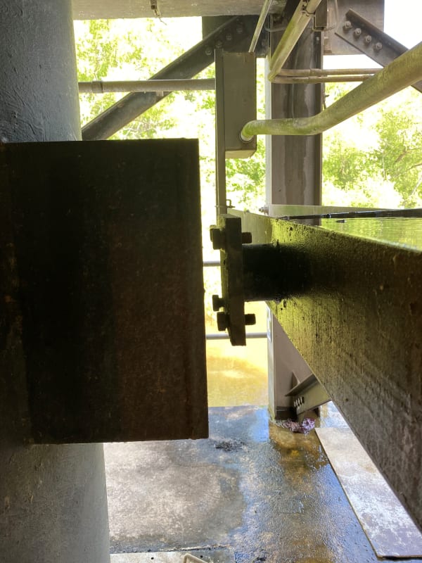
Finally, the existing pumps have a gap between the brace and the supporting steel as shown below.
Existing_Brace_a8eiui.jpg

I am no expert in this field, have only been a full-time engineer for a little over a year, but I would think this confirms the thinking that if the new brace is the same type as the one shown below that it is for dynamic/vibratory issues and not for any static load. There is an expansion joint at the discharge nozzle as well, could it be some type of safeguard if the tie rods fail and the expansion joint tries to expand from the internal pressure?

I would love to be able to perform a dynamic analysis on this system but it's not within the scope of the project, nor does our office/myself have the technical know-how to perform this type of analysis. Just doing the static analysis and trying to explain how the support stiffness needs to be within a least an order of magnitude for an accurate solution was hard enough. Trying to correctly model the boundary conditions/boundary stiffness's is certainly not within our capacity at the moment.

I couldn't find any information in the pump IOM or online about this type of brace, so I second all those above who asked if anyone else has more information about this design element I would be very interested in learning more about it.

Cleaning up some comments above
This will be a new installation, it does have a bolted flange on the nozzle, and we have double checked the minimum submergence.
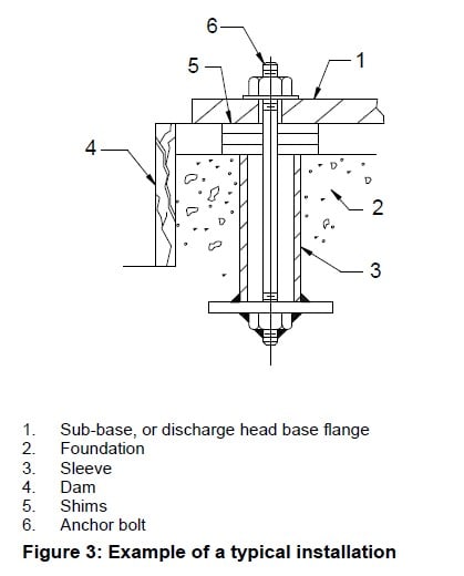
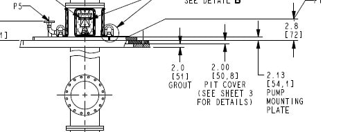
The typical installation shown below for mounting on concrete does show shims, but we haven't gotten the specifics from the manufacturer. I will update when/if we get more information.
Typical_Installation_omt7e2.jpg
 
I'll just wander in here with a random thought/question since we have been speculating about the purpose of the brace.

The horizontal fluid momentum is zero at the entry of the pump, while it is non-zero (directed to the right in first drawing) at the discharge of the pump.

That change in fluid momentum creates a reaction force to the left on the pump casing:
F = d/dt(m*v) = (mass flow rate) x (discharge velocity)

Isn't it possible/likely that the brace is supposed to help restrain the pump to avoid movement from that reaction force, without putting a moment load on the pump mounting plate and without loading the discharge pipe (especially if there is no piping support on pump side of discharge expansion joint). From the location of the brace, that seems more likely explanation to me. It is in a perfect location to absorb that force near where it occurs at the 90 degree elbow bend within the pump. But it is not at a good location for anti-vibration reasons. Anti-vibration braces (for tuning resonances) are often at location of highest movement. Since this structure is supported at the top, an anti-vibration brace for the first mode would likely be more effective near the bottom of the structure (or at location of a bearing near the bottom) This brace is only a short distance below that top mounting plate, it would be unlikely to change any vibration unless you had a bizarre higher order mode you were trying to address.

It doesn't seem unreasonable that you should be able to ask the OEM why they are putting in this brace that was missing (not connected to anything) in previous pumps.

As far as your original question, I have no idea. I don't understand what is supposed to be represented by these nozzle loadings.
=====================================
(2B)+(2B)' ?
 
electricpete,

Thanks for the response, we had a meeting with the pump manufacturer last week and their reasoning for the brace was to provide additional support due to:
[ul]
[li]The static/thermal nozzle loads we provided from the stress analysis.[/li]
[li]The load due to the change in fluid flow direction, they didn't go into detail but I assume it's very similar or identical to what you've outlined above with the change in momentum.[/li]
[/ul]

It goes back to the distance from the discharge nozzle to the mounting plate that creates a larger moment arm and requires additional thickness/support for these types of pumps. It doesn't show to scale in the drawings above, but the nozzles are a little over eight feet down from the mounting plate. You are also correct in assuming that there is no piping support on the pump side of the discharge expansion joint. The expansion joint itself is tied and the nearest pipe support is downstream of the expansion joint.

I do not have much experience with vibrations, asides from college courses and senior design, but I could see how the first natural frequency would produce oscillation at the pump's suction side at the very bottom. I do not know what the natural frequencies are though, and with a fixed motor speed it may be that the second or a high frequency would occur at the operating condition with a high displacement closer to the discharge nozzle. Their outline drawing states the following as well. "The pump assembly has been designed so that its natural frequency responses avoid the specified motor speed by an adequate safety margin. The design assumes a rigid foundation." Their safety margin is +/- %25, and they are working with the structural team to get a better foundation stiffness than assuming it to be rigid.

I can try to get mode shapes/resonant frequencies for the pumps, am still working on getting a direct line of communication with the pump manufacturer's technical team.

My original question has been put back on the manufacturer for them to provide us with any structural loads that would result from the brace. My thinking with the original diagram was to try and figure out what the force balance between the nozzle loads from our stress analysis and the nearby supports would look like at least conceptually if we were going to calculate the structural loads.

I guess the topic of this thread has gotten away from its original purpose, but I really appreciate everyone's responses as this is all still very new to me and there's a lot I don't know about pumps/piping. Will continue to provide more information as requested for those who wish to know more.
 
Thanks for the response. I'm not a pump guy but I sit next to one. My thoughts on your question fwiw:
Finally, the existing pumps have a gap between the brace and the supporting steel as shown below
A brace with a gap seems non-sensical to me.
It looks like there was an option to bolt an intermediate piece that wasn't used.
I am no expert in this field, have only been a full-time engineer for a little over a year, but I would think this confirms the thinking that if the new brace is the same type as the one shown below that it is for dynamic/vibratory issues and not for any static load.
A brace with a gap would not affect the dynamic characteristics except for very large movement which seems unlikely... leads to your next point...
There is an expansion joint at the discharge nozzle as well, could it be some type of safeguard if the tie rods fail and the expansion joint tries to expand from the internal pressure?
The bolts argue against that. What purpose do they serve? None unless to bolt an intermediate part which is not present. Further, if this bracket was used as a backup for this catastrophic failure that you describe, then those bolts should be removed because the bolt heads are going to concentrate the force over a smaller area, right? I wouldn't think the bolt heads would be sticking out like that if the support was intended to carry load in this backup scenario.

EDIT - Whoops, the scenario I didn't consider about those bolts is maybe the bolts are gap adjusting devices (in tapped holes). Seems unlikely but you never know. Maybe a look at the hidden (from photo) face adjacent to those bolts would provide a clue about their function.


=====================================
(2B)+(2B)' ?
 
electricpete,

I too have wondered whether it's possible that it was a provided feature that was never used for the existing pumps. It was installed over forty years ago so information is slim except for some old layout drawings. A brace will need to be utilized on the new pumps though per the manufacturer.

For your comments above, the expansion joint will be included in the new system for vibration damping between the pump and the piping. The size of the expansion joint ("18) with the working pressure (60 psig) of each pump would result in a thrust load of over 10,000 pounds as well, and there was no way we could have a horizontal load that large be supported by the existing structure without serious modifications.

I think you're right that it doesn't make sense for that brace with that gap size to serve as a backup restraint in case of failure from the expansion joint. Just a WAG on my part to try and find a reason for it being there and having some useful function.
 
"The design assumes a rigid foundation." Their safety margin is +/- %25, ......."

I'd ask where this "rigid" foundation is AsSumed to begin for the pump "assembly" design.
- Out at the edges of the 2500 lb, 2 " thick pit cover covering a (scaled) 3.5 foot opening?
- At the pump mounting flange that is bolted to the 2500#2"TPC ?

What are the specifics of the acceptance vibration specifications?

So far it seems like this is not a variable speed pump. (confidence level, 15%)
 
I think Tmoose comments illustrate the complexity of defining a boundary condition that was mentioned earlier. He knows that stuff way better than me.
abot93 said:
For your comments above, the expansion joint will be included in the new system for vibration damping between the pump and the piping. The size of the expansion joint ("18) with the working pressure (60 psig) of each pump would result in a thrust load of over 10,000 pounds as well, and there was no way we could have a horizontal load that large be supported by the existing structure without serious modifications.
So none of the previous pumps had expansion joints, but the new one does have an expansion joint and they’re adding the brace to go with the expansion joint?

I think I understand what you’re saying. Pressure times area force is 60psig * pi* (9”)^2 = 14,580 lbf. If the expansion joint has pipe supports on the piping side but not the pump side than that force goes to the pump casing. It would be acting in the same direction as the fluid momentum change reaction force (to the left in the first drawing). gage pressure psig is appropriate because it represents differential to the atmospheric pressure pushing back on the other side of the casing. BUT all of that assumed the tie rods don’t carry any load during normal operation. I’m not sure of the role of expansion joint tie rods in general… do they continuously carry load or are they only a backup? Does it vary by application? If they continuously carry load it seems like that defeats the purpose of expansion joint although maybe they can still isolate vibration somewhat, I'm not sure.

A note on terminology - I wouldn’t call it “thrust” load because in the lingo of rotating equipment, the word “thrust” is reserved for forces acting in a direction parallel to the shaft axis (not that it’s logical, that’s just the terminology).


=====================================
(2B)+(2B)' ?
 
Status
Not open for further replies.
Back
Top