Continue to Site

Eng-Tips is the largest engineering community on the Internet

Intelligent Work Forums for Engineering Professionals

  • Congratulations GregLocock on being selected by the Eng-Tips community for having the most helpful posts in the forums last week. Way to Go!

How to calculate Section Modulus on Compression Side of Beam??!! 3

Status
Not open for further replies.

Struct_Dre

Structural
Mar 29, 2019
48
Hello Everyone!

I'm very aware that this may seem like a very stupid question, but I'm stumped so please be kind LOL.

I am designing an aluminum beam for the first time and I need to check the interaction between local buckling and lateral-torsional buckling.

When Fe (flange's elastic buckling stress) is less than Fb (the lateral-torsional buckling stress of the beam) the 2010 Aluminum Manual requires that formula F.2-11 be used to reduce the LTB strength of the beam.

This formula contains Sc.

Sc is the section modulus on the compression side of the neutral axis of the beam.

I have NO CLUE how to find Sc. I assume the formula looks something like Sc=I/y. "I" being the moment of inertia for the entire section and y being the distance from the neutral axis to some point on the compression flange (top flange).

Is this correct?

If so, is y the distance from the neutral axis to the top of the compression flange or is y the distance from the neutral axis to the bottom of the compression flange??

I am extremely confused, have somehow never even heard of Sc in all of my short career, and can't find any examples online. Please help ASAP.

Also, I am designing an Aluminum Association Standard Channel, simply supported with UDL on top flange.

Any help is appreciated!!! :)
 
 https://files.engineering.com/getfile.aspx?folder=ca5ea31b-c970-4c17-be52-12c106d6a17f&file=Sc_Question.JPG
Replies continue below

Recommended for you

Wait...I just decided to google the definition of section modulus and I got "The moment of inertia of the area of the cross section of a structural member divided by the distance from the center of gravity to the farthest point of the section; a measure of the flexural strength of the beam."

So that means y=the distance from the neutral axis to the top of the flange.

Please correct me if I'm wrong.
 
For positive bending moment (compression on top) y is the distance from the N.A. to top of flange. For negative bending moment, y is the distance from the N.A. to the bottom of flange.

'y' is measured to the farthest point of the section which is in compression.

BA
 
Struct Dre said:
So that means y=the distance from the neutral axis to the top of the flange.
Please correct me if I'm wrong.

Edit: The following does not apply for aluminum. I stand corrected.

This is one of the rare times I'll have to disagree with BA. The definition you googled is correct, but you are misinterpreting it:

"Distance from the center of gravity to the farthest point of the section" is correct.

What you are missing is that the point is literally the farthest point... located anywhere on the section without regard to whether that point is top, bottom, compression side, or tension side.


[idea]
 
BA is correct. Every section has a section modulus for compression, and another section modulus for tension. I use "c" instead of "y", but that matters not.
 
I agree, BA is correct. A cross section can have two section modulus, we used to call them "Stop" and "Sbottom", which will have different numerical values for unsymmetrical sections. The "top" and "bottom" refer to cross section above, and below the neutral axis respectively. You have to use the correct one for the case under consideration.
 
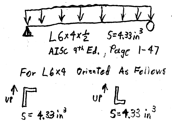
Hmmm... maybe I may need to learn something. Here's an example of what I have been doing:

L6x4-600_kjiaer.png


Are there different values of S for the two orientations?
If there are, why doesn't the AISC Manual note this?

[idea]
 
AISC takes the min of either tension or compression side S for design purposes.

But aluminium design is calling specifically for the compression based modulus.

You need to be clear it's calling for the elastic modulus, and not the plastic, or effective plastic modulus I guess as well. Some design guides internationally interchange Z and S nomenclature when discussing elastic and plastic moduli.

 
Agent666 is correct.

For the L6x4x1/2, I = 17.3, for long leg up, yb = x(bar) = 1.98, Sb = 17.3/1.98 = 8.74; and yt = d-x(bar) = 6-1.98 = 4.02, St = 17.3/4.02 = 4.3.

For angle, the resulting stress is the average stress.
 
SRE,
Note in your example that the value listed for S is not I/y as shown in the tables, but (I/distance to end of long leg), so it applies to that leg, not the outstanding leg. Smax is 17.4/1.99 = 8.74.

The same applies regardless of material.

Edit: I typed before seeing the post by retired13. But "average stress" is not applicable. The stress on the long leg would be about twice the stress on the short leg when bent about the strong axis.
 
hokie - For steel. Since "I" = 17.4 in4 is for the entire cross section of the angle (including the outstanding leg).
and​
Distance to the "farthest fiber is 6" - 1.99" = 4.01"

Wouldn't "S" for the entire section (including the outside leg) be 17.4 in4 / 4.01 in = 4.34 in3 ?

I'm not disputing you, just wondering if I have been wrong about this for well over four decades.

[idea]
 
Yes, I think you have misunderstood. S is not for the entire section, it is for the extreme fiber. M/S is the stress, but stress varies throughout the depth of the section, and is zero at the neutral axis. That is why I prefer the more general use of Mc/I, where c is the distance to any point where you need to determine the stress.
 
For simply support angle with long leg up, Sc = 4.3, with long leg down, Sc = 8.74.

The average maybe is not a good word, basically I wanted to distinguish the stress calculated using conventional axes and the principal stress. Which shall be considered for angles.
 
@BAretired, THANKS SO MUCH!! That really clarified that for me. Now I completely understand. I really appreciate everyone's help :)
 
Thanks, hokie and retired, I'll work towards understanding unsymmetrical section bending.

Struct Dre - I apologize for hijacking your thread, I'll start a new thread if I have questions for hokie, et. al.

[idea]
 
One caveat I'll add to hokie66's response is that it is only Mc/I for symmetric (principle axis) bending for unsymmetric (non-principle axis) bending such as with angle shapes the general formulas should be used:
σy =( (Mx Iyy - My Ixxyy) / ( Ixx Iyy - Ixxyy^2) ) * dy [ General Elastic Bending Stress Formula which captures non principle axis bending, if Ixxyy = 0 reduces to the common stress formula = Mx dy /Ixx ]
σx =( (My Ixx - Mx Ixxyy) / ( Ixx Iyy - Ixxyy^2) ) * dx [ General Elastic Bending Stress Formula which captures non principle axis bending, if Ixxyy = 0 reduces to the common stress formula = My dx /Iyy ]


My Personal Open Source Structural Applications:

Open Source Structural GitHub Group:
 
@SlideRuleEra No worries! That's what this place is for! [bigsmile]
 
Celt83,

OK, but you can bend an unsymmetric shape about other axes than the principle axis. As to angles, we normally work with the strong axis and weak axis taken based on parallel to the legs, and that is good enough for structural engineering work, which is an imprecise discipline.
 
its principAL

another day in paradise, or is paradise one day closer ?
 
Status
Not open for further replies.

Part and Inventory Search

Sponsor