Continue to Site

Eng-Tips is the largest engineering community on the Internet

Intelligent Work Forums for Engineering Professionals

  • Congratulations waross on being selected by the Eng-Tips community for having the most helpful posts in the forums last week. Way to Go!

Capacity check for embedded angle in concrete wall

Status
Not open for further replies.

TeemoshenksEIT

Structural
Jul 30, 2020
15
CA
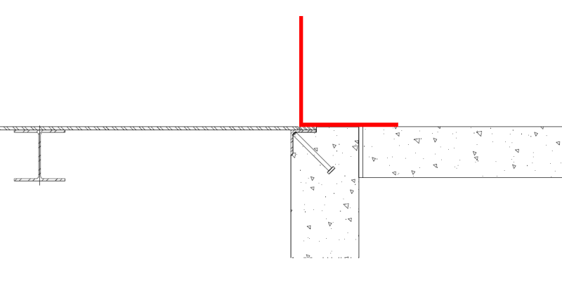
I am designing an electrical trench with floor elevation at -4'-00". This pit has a false floor at elevation 0'-00", for which I have placed beams to pick up electrical equipment and steel plates.Some of the equipment are near the trench wall and hence I need embedded angles in the trench wall to which I am welding another angle that will pick up the equipment along with the floor plates. For the connection of the angle to the embedded angle, what I have thought of is to make slotted holes every 12" along the connecting angle and plug weld it to the embedded angle. I have attached a quick drawing I made to show you guys what I mean.

I have a couple of questions:
1. How do I check the capacity of the embedded angle? Do I check anchorage for this?
2. As the connecting angle (supporting the equipment) is laterally restrained, I can't see it bending. However its toe is in compression so Local leg buckling and leg yielding is possible, right?

Thanks for the help everyone.
 
 https://files.engineering.com/getfile.aspx?folder=1271882e-0569-4c77-8250-cdb4e4a966f8&file=embed_angle_connection_detial.pdf
Replies continue below

Recommended for you

The embedded angle has no problem, because it offers no strength. The problem is the headed stud. You shall apply the load to check the concrete breakout strength. If it is possible, you shall provide angle/beam across the trench width with support on the trench wall.
 
Thanks retired13. I did mean to say anchorage for the headed stud, my bad. When I am checking concrete breakout resistance of the headed stud in tension, do I increase my tension force from the force couple by 1/sin45 to account for the stud being oriented at 45 degrees?
 
How thick is the wall? Does a floor slab extend over the wall? That would be the usual case.

BA
 
Hi BA, the floor slab is not connected to the wall, there is an expansion joint between the trench wall and floor slab. The trench wall is 8" thick.

The load on the welded angle is 0.2kip/ft.
 
OP said:
How do I check the capacity of the embedded angle? Do I check anchorage for this?

Probably with some difficulty and creativity. If there's a modern, accepted procedure for doing anchorage checks on studs coming into a corner like that, I don't know of it. You may have to jury rig provisions intended for the usual, anchor perpendicular concrete surface condition or apply some judicious engineering judgement.

Does the embedded angle already exist? If not, would it be acceptable to bolt an angle to the wall without the embedded elements? Slotted welds will be difficult, albeit not impossible, to execute in a vertical position. Moreover, I don't believe that slotted welds are supposed to resist tension demand by the book. That said, depending on your you're viewing this, there may not actually be a tension demand.

OP said:
As the connecting angle (supporting the equipment) is laterally restrained, I can't see it bending. However its toe is in compression so Local leg buckling and leg yielding is possible, right?

I do see it bending as, in most instances, I would be unwilling to hang my had on the lateral restraint that you mentioned. In order to best help you here, I feel that we'll need to collectively get a handle on what we think the statics of your situation are. Were you to truly have no bending in the angle, you would also probably have no anchorage demand in your studs. Convenient... if it's true.

I don't see locally buckling of the non-embedded angle being an issue unless your weld spacing is so great that you develop appreciable, principal axis flexure in the angle via bending between fastening locations.

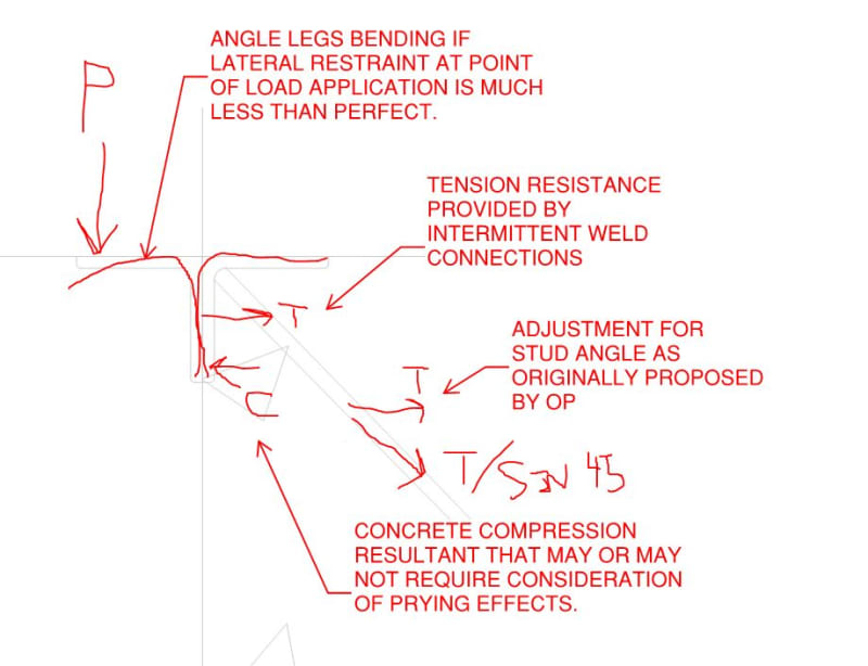
In order to best help you, I feel that we should all get a handle on what we think the statics of the situation is here. Is the sketch show below close to how you're envisioning the situation? Full disclosure because the truth is important: I suspect that this is a connection that most engineers just eyeball rather than rigorously design.

C01_tr45lr.jpg
 
Hi Kootk, I completely agree with your markup. That is exactly how I am envisioning the forces.
 
[smile] Kootk's drawings are becoming more captivating every day. [smile]
BA
 
Bluebeam makes me lazy... I used to be celebrated for my high quality pencil sketches. Still, time is always a constraint and I figure it's better to answer sloppy than not answer at all. And I am this forums most prolific sketch poster, bar none. So there's that.

The next trick, I think, is to:

1) Attempt to accurately predict the likely breakout failure mode and;

2) Try to figure out a simple, yet conservative way to cover #1.

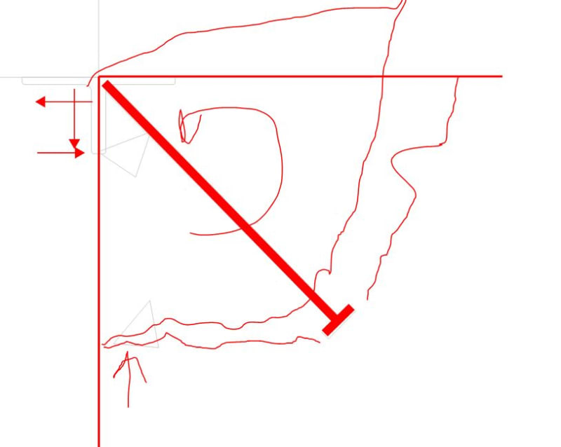
The sketch below is my first stab at #1. I see mostly pryout.

C01_zbu6av.jpg
 
Kootk, yes I agree, concrete breakout in tension will govern. That's where I got stuck, I wasn't sure how to resolve the tensile force for the stud to use the Appendix D equations. I do think resolving it to T/sin45 would be conservative.
 
OP said:
Kootk, yes I agree, concrete breakout in tension will govern.

It sounds as though we disagree as I feel that it's a pryout mechanism that will govern. Granted, the mechanism resisting pryout will be concrete tensile resistance.
 
Sorry Kootk, I agree with you pryout shall govern. Lot more material to go through for breakout in tension.
 
Provide a cross member, then you can sleep well.
 
Can you do something like (likely cheaper and easier; it avoids pryout and plug welds in confined space, etc.):

image_ewewf2.png


Dik
 
retired13, could you elaborate on the cross member? I don't think I understand how it may help.
 
I like Dik's idea and don't understand the objection. It is the way I have always handled this situation.

But if you really need something projecting inside the wall, use Dik's solution with a continuous plate welded to the angle and projecting as far as required.

BA
 
BART: It's one of my 1000s of standard details... used it for years. Unless there's something about the equipment that relies on the trench being flush... I'd try to work around it... plug welds in the field are a little pricier than welds in a shop... also if the assembly has to be HDG or something. Unless the equipment is continuous, it would be cheaper to notch the plate out for the equipment.
Even a BAR 1/2 x 1 with intermittent fillet welds would be less costly than the field plug welds, I suspect.


Can you move the equipment or trench?

image_fyqsgb.png


Dik
 
Similar to dik's idea, but use an angle with one end connected to the I beam, and to the trench wall at the other end. Select an angle with adequate depth, so you can cope the upper leg, and connect it to the I beam by bolt connection. Do the similar to connection on the wall side - weld a piece of bend bar with pre-drilled hole to the edge angle, and bolted to the cross member. This is the positive load supporting method commonly seen in equipment room trenches.
 
Status
Not open for further replies.

Part and Inventory Search

Sponsor

Top